

Sachs Care!
by Doug Wilford
Originally printed in the 2001 issue #12 of Still….Keeping Track
The Sachs engine is very reliable and will shift as good as any motorcycle engine, IF you take care of it!
The Pentons we have today are not new out of the crate, and what I am finding is most of the main shafts (Counter Shaft Sprocket Shafts) have the speedo drive ears broken off. This is a bad situation and can cause a lot of problems in shifting, wear, and letting dirt into the transmission.
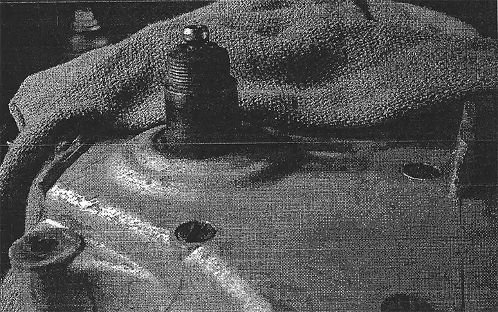
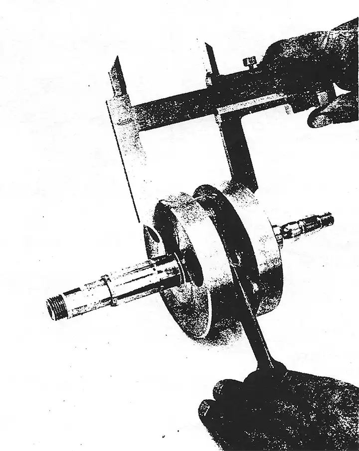
Illustration #1, is a shaft, without the ears, when the tranny is in high gear. Notice the selector rod is showing, allowing dirt to accumulate and be drawn back into the engine when shifting to a lower gear.
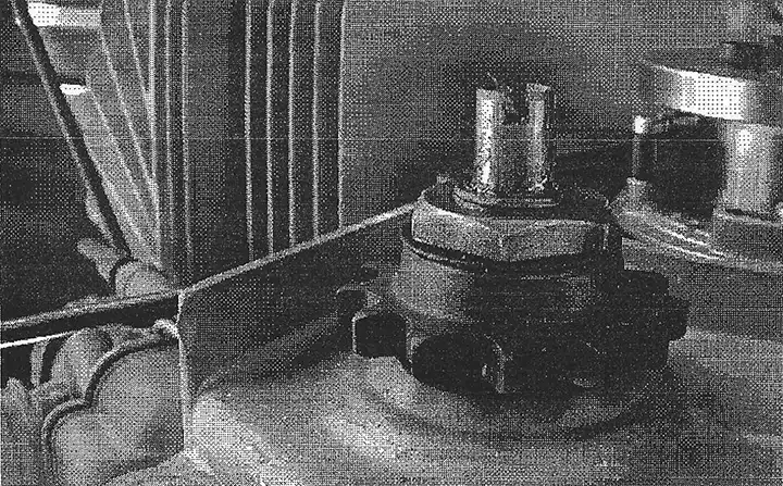
Illustration #2, is a new or unbroken shaft. Notice the selector rod does not show. This part now has a surface that the seal in the right side cover can seal to.
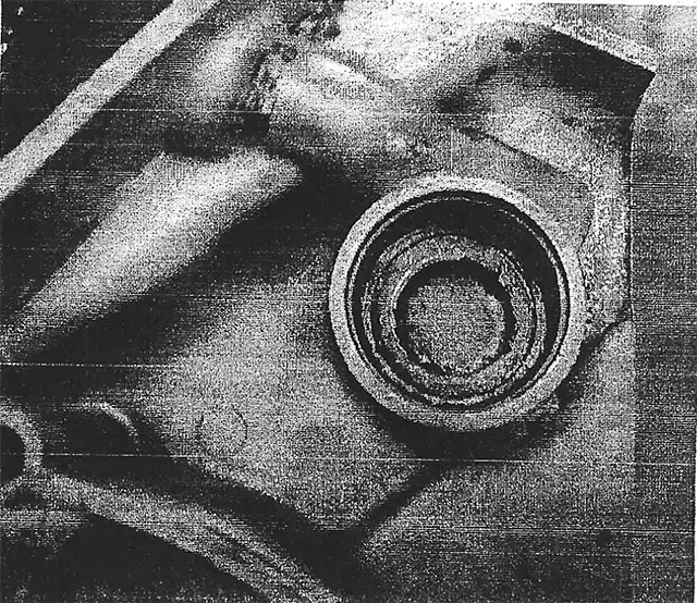
Illustration #3, is the right side cover with out a seal
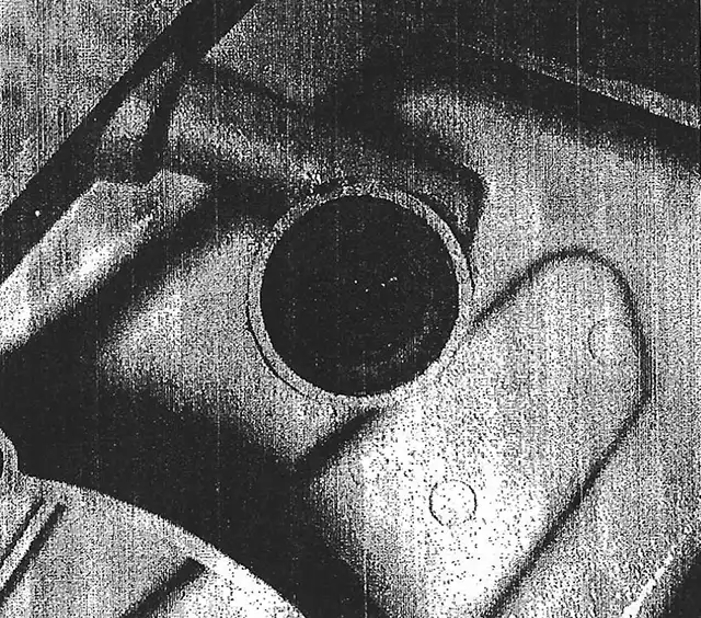
Illustration #4, is a right side cover with the seal. This is the proper set up a complete shaft which will be sealed by the cover preventing dirt etc. into your bottom end. If you want reliability, I highly suggest the combination of Illus. #2 and Illus. #4 . That is how it was meant to be, with also the means to drive the speedometer gear.
by John Cobb
Reprint of "Let's Do It Right" April 1973 issue no.5 of "Keeping Track" newsletter (PDF available here.)
Now that you won the race, how to prepare so you'll win next week again.
First remove air box cover and filter, put rag in carburetor boot.
Next wash the bike as soon as possible. Right after the race is best. Because if it was a muddy race the mud will wash off faster while its wet. Wash the bike thoroughly, lay it on its side and wash underneath it. Pull the tank and seat off and wash them off. Remember if you wash it good when you are going over it and you find if you have to pull the engine it will be much easier because it is clean. Also it will save much time cleaning the outside of the engine after its out. Reinstall gas tank and start engine. Run for 10 minutes. Now that its clean lets start preparing it.
Leave the seat and tank off. Take the front and rear wheels off and check the bearings, clean the brakes. Grease the brake cam, making sure it is not too sloppy in the backing plate. With sand paper lightly sand the brake drums and shoes. Check the spokes and trueness of the rims. (I know most people don't have a wheel truing stand, but a vise will work). Put the axle in the wheel and tighten the axle in the vise. Get a piece of wire and mount it along the work bench so its a little ways from the rim. Spin the wheel. Tighten spokes accordingly to true up rim. Check the tires for wear and cuts. Also be sure the valve stem isn't being pulled out by the tire spinning on the rim. On the rear wheel be sure and check the rubber bushings. If worn or cracked replace them; it could save you buying a new rear hub later. Check the rear sprocket carrier bearings making sure they are tight and well greased. If you have to remove the bearings to repack with grease or replace, make sure to heat the aluminum around the bearing and tap out lightly. If you don't take care doing this, the new bearings may be loose in the sprocket carrier.
Now, check sprocket teeth for wear.
While the rear wheel is off, check swing arm and bushings. See if you can move the swing arm back and forth or sideways. If so, either the swing arm bolt is loose or bushings are bad. Check the shocks for being bent or leaking. Now you can replace the rear wheel. Don't put the chain back on yet. Wash it off good with solvent or gas and soak it in oil until you are ready to use the bike again.
While the front wheel is off, check the fork head bearings. If you have back and forth movement or tight spots, it's best to remove the triple clamps and inspect bearings and races. Repack and tighten them. If its been 4 or 5 races on the same fork oil, you should change it. Flush the forks out with solvent and refill. 135cc for the C.M.F. (32mm Ceriani forks) and 200cc for the steel gas tank model pre 71 (and 200cc for the 1974+ 35mm Ceriani forks). Replace front wheel.
Remove the carburetor, clean and inspect thoroughly. Check air box for cracks, make sure there's no dirt inside, (clean) and replace filter if necessary. If it's a muddy race, make sure the filter element is paper and well sealed. Remember, care should be take here. If dirt or water pass thru the filter and air box, it will ruin pistons, rings, rods and cylinders, just to name a few. So take care.
If you have about 6 races on the engine, pull the top end off and inspect cylinder, piston, rings and rod for wear. Also take the tip off exhaust pipe and clean baffle in it. This can plug up causing poor engine performance.
After 3 or more races or enduros or any real wet race, you should change transmission oil. The best way is by removing the clutch cover (on the Sachs motors) and tipping the motorcycle on it's side to drain oil. Doing it this way you can inspect the clutch gear and primary drive gear. With the cover off see if you can tip the clutch wheel back and forth. If so, the bushing in it is probably bad and should be replaced. Before putting clutch cover back on, pour in 3/4 Quart of transmission oil. This is more than the book calls for but won't hurt a thing.
Pull mag cover off and inspect Motoplat, making sure it's clean and dry. Leave the mag cover off util you are ready to race again. This will let everything dry out good. Check the front sprocket and teeth while the cover is off.
Check the coil mount, making sure its tight and grounded properly.
Now go over the whole bike checking and tightening every nut and bolt on it, making sure motor mount and swing arm bolts are tight. Reinstall gas tank making sure the padding is in the right place so the tank doesn't beat against the frame. Put foam rubber blocks between seat and tank and over (not in front of) are intake opening. Now push seat in place and tighten. You should be pretty much ready to go. Don't forget to oil cables and levers. This sounds like a lot of work but if you want to be a winner it takes a lot of work!!
Editor's note: Since this article was written in 1973, I took the liberty of updating parts of it for our readers who have bikes produced after this time period Additions to this article are printed in italics. Although this article is 50+ years old, it still holds true for anyone riding their Penton today.
by John Cobb
Reprint of "Let's Do It Right" Jan 1973 issue no.2 of "Keeping Track" newsletter (PDF available here.)
Generally, this article could be a base for most piston work, but it is directed toward our Penton owners and their machines.
First, when should you rebore or replace a piston?
- On a 100cc Penton, when you get .005" clearance.
- On a 125cc Penton, when you get .005-1/2" to .006" clearance.
- On a 175cc Penton, when you get .006" to .007" clearance.
- On a 250cc Penton, when you get .006" to .007" clearance.
- On a 400cc Penton, when you get .006" to .007" clearance.
Now here is how you measure the piston and what you will need:
1. Most people do not have micrometers, which is the most accurate way for measuring the piston clearance, but if you do have access to one, use it.
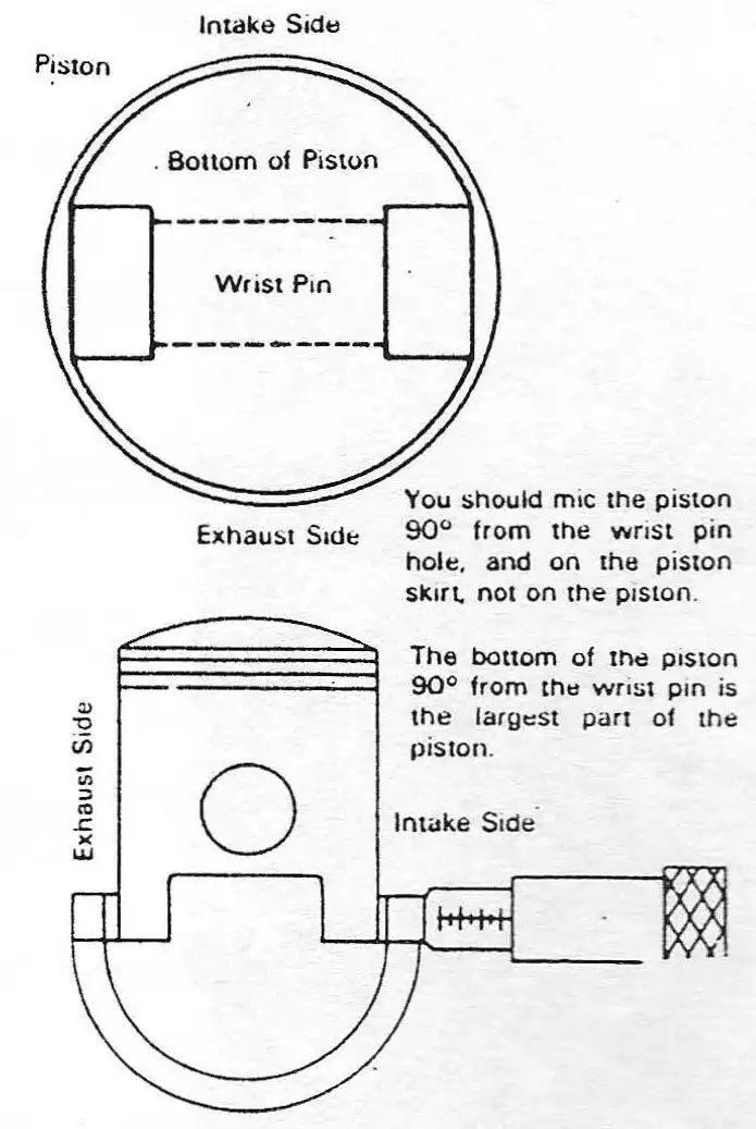
In otherwords, the piston is built in the form of a taper and is shaped like an egg. The largest part being the front and back at the bottom of the piston.
2. Now you know the piston size. We have to find out the cylinder size.
The cylinder is not tapered or egg shaped and should not get this way. It shouldn't have any grooves in it where something has broken and was tearing up the cylinder wall. A good cylinder should have a good cross hatch pattern.
To check the size of the cylinder, you should have an inside micrometer. But if not, we can still check piston to cylinder clearance. What you will need is a feeler gauge.
A. The best way is to take the rings off the piston, and insert the piston in the cylinder the way it would normally run. After doing this, try putting the blades of the feeler gauge in between the cylinder wall and piston. Do this until you get a drag on the blade. See how many thousands it has, and you will know the clearance.
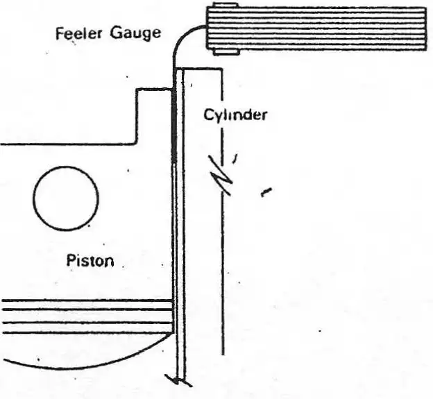
The clearance should be checked at the top of the cylinder and the bottom. This is to see if there is any taper.
B. The most accurate way is with an inside micrometer and it should always be used whenever possible. The way it is done is by inserting the inside micrometer at the bottom and checking the size, then do the same at the top. See if there is any difference between the top and bottom. If there is, you will know how much taper the cylinder has.
C. Now, you will need to know the clearance between the piston and cylinder using an inside micrometer. The best way is to take the largest reading off the cylinder, then the piston reading, and subtract it. You will then have the clearance.
EXAMPLE: Cylinder reads 2.128, Piston reads 2.121. The difference is .007" clearance.
The clearance is too much.
Note: If there is very little taper to the cylinder like . 00 l" and the clearance between cylinder is . 003" this small amount of taper will not hurt.
D. All measurements taken on the inside micrometer should be retaken on the outside micrometer to be accurate and less possible chance of mistake.
3. Now let say you found .005" clearance between piston and cylinder (which is borderline on a 125cc).
A. Look at the cylinder. If the cross hatch is still in it and there are no bad scratches, the cylinder is probably all right and not worn. So take the piston and mic it, and then mic a new one of the same size. If the new one is . 002" larger than the used one, this would give you .003" piston to cylinder clearance, which is good. So you would just break the glaze in the cylinder with a surface hone and install a new piston and rings.
B. A piston will usually wear more than the cylinder, because it is made of aluminum. By checking pistons for wear and not having to rebore, you will get much longer cylinder life.
4. Lets say the cylinder to piston clearance is within limits and a rebore is not needed. That does not mean the piston is in good shape.
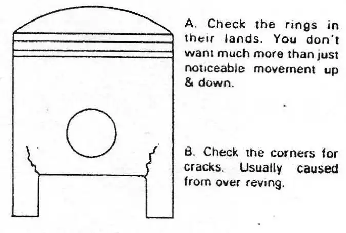
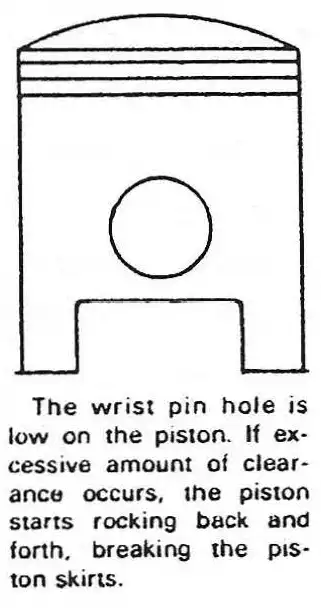
On our 175cc Jackpiner the clearance should be checked often. Keep a close look for cracks on the piston. Remember if a piston skirt breaks off, it may cost you a new cylinder, connecting rod, piston and possibly a set of cases. The reason the 175 is more critical, is the way the piston is made.
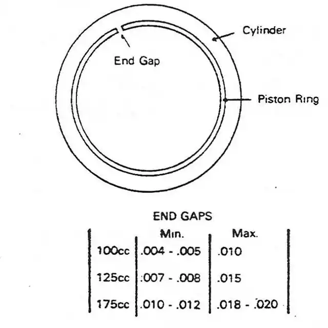
5. Piston rings and piston clearances.
A. Piston rings should have noticeable up and down movement in their ring lands, which is about . 002" movement. If excessive amount of up and down movement is found, the piston should be replaced. Whenever installing new rings, be sure and check this, plus end gap. this wear in ring lands comes from dirt, water and high R.P.M.'s (over revving).
B. End gap. This is checked by inserting just the ring in the cylinder. You should put the ring in square in the cylinder about 1/2" to 3/4" down from the top of the cylinder. Then take a feeler gauge and check the gap. Check both rings. Usually you do this if you are only replacing rings and using an old piston. Be sure and clean all carbon from ring lands before installing new rings on the piston. Ring end gaps for 250 & 400 should not exceed .027" (0.7mm).
C. Piston to cylinder clearances for reboring cylinders:
100cc - .0015" to .002"
125cc - .0025" to .003"
175cc - .003" to .0035"
250cc - .0025" to .003"
400cc - .003" to .0035"
These are the clearances you should use when reboring cylinders.
Editor's note: these measurements are for the Mahle pistons. When using a Wiseco piston, bore the cylinder slightly larger to allow for piston expansion when it heats up. This will prevent it from seizing up in the cylinder
Remember, whenever you rebore a cylinder, be sure and round or radius the top and bottom edges of all ports. This is so the rings will not catch in the port and break them causing much damage. Remember, every little thing counts in reboring. A cylinder and piston set-up properly will give good power and reliability for many hours.
99% of piston and ring wear is dirty air, water and excessive high R.P.M.'s. Your cylinder and piston are only as good as the air filter system. Keep your air box and filter very clean and well sealed from dirt and water.
by Alan Buehner
Originally printed in the 2000 issue #9 of Still….Keeping Track
Magnesium is a strange material that was used in many parts of the Penton motorcycles. It was used primarily in the wheel hubs and motor cases. When heated, this material expands. I got to see this firsthand when I took a KTM motor case in to have a crack welded. Yes, magnesium parts can be welded, however, this should be done by an expert who has the right equipment and magnesium welding rod. I put on a pair of welding goggles and watched as he proceeded to weld up the crack. As soon as the arc touched the metal it lit up with a bluish-green glow that immediately heated up the metal and caused the crack to open up (like a miniature grand canyon). The welding rod was used to fill the crack in and another amazing thing was that unlike steel which stays burning hot after being heated up, the magnesium immediately cools down and can be handled almost right away. The main point that I am trying to make here is that when magnesium is heated up, it expands. When trying to remove and install bearings and seals from magnesium parts, heat the magnesium up first with a propane torch and the bearings and seals will slide in or out very easy. Do not force bearings in or out of "cold" cases. This will cause wearing on the surfaces and will result eventually in a loose fit where they will spin or fall out.
NOTE: for safety, do not use torches or open flames around flammable materials in your work area.
Do not use excessive heat on magnesium. If magnesium gets too hot, it will literally bum itself up (self destruct). If you take magnesium parts to someone to have welded, make sure that you let them know that it is magnesium and make sure that they have the experience and equipment to weld it.
Do not use Armor-All cleaner on alloy and magnesium (e.g. wheel hubs and rims). This will cause immediate oxidation of the metal and if left on for a period of time will eat away at the metal. Read the labels on any products before using them on magnesium and aluminum. Experiment by using any chemicals on a scrap part first to see what happens.
Do keep the magnesium parts painted. This will keep them from corroding. Corrosion of magnesium is evident from the formation of a white powder around the affected area. This results in pitting which eats away into the metal.
When disassembling or reassembling motor cases, do not force them. Check to make sure that all of the screws holding the cases together have been removed and make sure that an internal part has not moved out of alignment and is preventing the cases from fitting together. Sachs and KIM motors are finely engineered and are designed to fit together precisely.
Do not use gasket cement in reassembling motor case halves. Doing so will not only make it difficult to separate the cases but will result in the destruction of the facings of the cases when the gaskets must be scraped off.
Do use a thin film of grease on the case halves and gasket surfaces to provide a tight seal. This allows the cases to be pulled apart easily. Soaking the gaskets in warm water makes them flexible and allows them to stick to the greased surfaces and stay aligned over the holes during assembly. Torque the case screws to proper specifications (5-8 ft lbs.).
A common problem with the KTM motors when they have been left setting around for years is corrosion in the crank area. One tip that I received a few years ago was to use 3BOND clear coat epoxy for coating inside crank areas.
I asked our Penton experts, Kip Kern of Indiana and Bobby Lucas of Texas for their ideas on how to fix a corroded crank area and they sent me the following suggestions:
Kip Kern
To clean magnesium parts I suggest the following:
Lightly glass bead blast parts at 60 psi with 80/100 grit glass bead (be sure that you wear eye protection and a respirator or dust mask).
Carefully inspect parts after blasting for cracks and weak spots. Pay particular attention to:
- Case screw hole areas (for cracks)
- Kick starter stop bolt area (splits around hole)
- Bearing/ Crank flange areas (cracks)
- Front/ rear hubs (splitting along seams from spokes being too tight)
- Ignition cover, bottom inside area (holes where moisture collected)
Wipe internal case areas down with a light film of heavy grease and rub it in well to seal the magnesium. I use acid etching primer on outside of cases followed by paint to seal outer cases. Remember, keep cases sealed internally and externally from the elements to prevent corrosion! Moisture is the enemy! Dissimilar metals can also cause corrosion.
To remove bearings: heat the cases slowly in a small electric oven at 300 degrees. and then press/ pull the bearings out using proper tools, pullers, or a press. Do not get in a hurry as you can damage the case material.
CAUTION: Remember to always have a fire extinguisher available or a fire plan ready when working with magnesium. Only allow trained, certified personnel to weld this stuff!!
- Do not use Silicone on cases
- Do not use Locktite on case screws upon assembly
- Be sure to clean between the motor mounts and the frame (remove paint) for proper electrical grounding - I use electrical joint compound/ grease on the motor/ frame contact areas to ensure that I have a positive ground for the ignition.
Bobby Lucas
Complete mechanical removal of corrosion should be practical insofar as practicable. Such mechanical cleaning should be limited to the use of stiff, hog-bristle brushes and similar non-metallic cleaning tools, particularly if treatment is to be performed in a home shop environment.
Any entrapment of steel particles from steel wire brushes or steel tools or contamination of treated surfaces by dirty abrasives can cause more trouble than the initial corrosive attack. Corroded magnesium may generally be treated as follows:
- Clean and strip the paint from the area to be treated.
- Using a stiff, hog-bristle brush, break loose and remove as much of the corrosion products as practicable.
- Treat the corroded area liberally with a chromic acid solution, to which has been added sulfuric acid and work into pits and crevices by brushing (with a non-metallic brush) the area while still wet with chromic acid.
WARNING: Chromic acid and sulfuric acid are hazardous chemicals. Be sure to read the labels and follow the instructions on the containers for proper use before buying and using. Make sure that you wear eye protection and suitable clothing and gloves. Make sure that the area you will be working in has adequate ventilation.
- Allow the chromic acid to remain in place for 5 to 20 minutes before wiping away the excess with a clean damp cloth. Do not allow the excess solution to dry and remain on the surface. Paint lifting will be caused by such deposits.
- As soon as the surfaces are dry, restore the original protective paint. Use at least two coats of Zinc chromate paint. When the metal's surface temperatures are above 250 degrees F, an extra coat of paint primer (minimum of three) should be applied ( crank area).
PJI offers a KTM engine paint that so far has held up on engines I've restored for the past few years. Remember that the inside of your engine is also painted. Pay attention to the inside of your ignition cover and always vent your magneto. Remove your ignition cover after you wash your bike and run up your motor for a good air drying.
by Alan Buehner
Originally printed in the 2000 issue #8 of Still....Keeping Track
In January, I contacted Greg Johnson of West Virginia who faxed me a copy of a Penton West Dealer Service Bulletin (no. 7) issued by Carl Cranke who was the Service Manager at the time. In my conversation with Carl at Sears Point in April, I asked him if his porting is just for enduro riding. His response was that it was good for any kind of riding. In talking to people who have ridden one of Carl's bikes, their response was that the power was available anywhere on the throttle and that it was controllable and predictable. The following is his porting specs:
- Set the deck height (distance from top of cylinder to top of the top ring) at 1.0 mm or .040 inches.
- Install a degree wheel and find top dead center
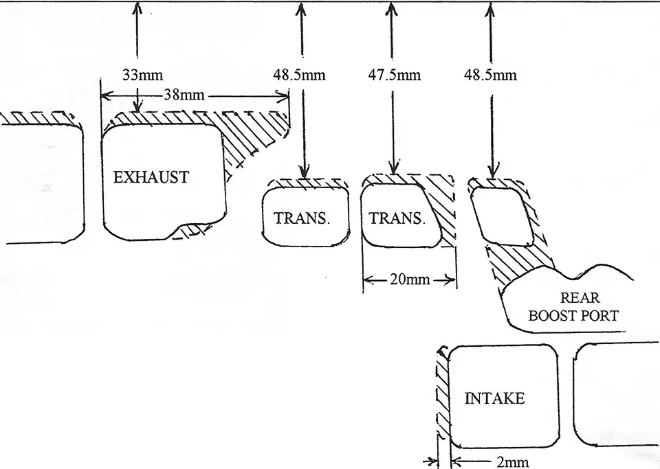
- Rotate engine clockwise 86 degrees and scribe a line above the exhaust port.
- Rotate engine 114 degrees A.T.D.C. and scribe a line above second set of transfer ports.
- Rotate engine 116 degrees A.T.D.C. and scribe a line above the front transfer and rear boost ports.
- Rotate engine 80 degrees A.T.D.C. and scribe a line on the piston along the bottom of the inlet port.
- Raise and widen all ports to the scribe lines according to the diagram supplied. (NOTE: be sure to radius exhaust port to top edge).
- Match and blend transfer port passages at bottom of cylinder to match crank cases.
- Match inlet manifold to inlet port. (Use gasket as a guide).
- Use an expansion chamber with the dimensions supplied.
- For tight race tracks, use an internal rotor ignition (timing 2.8mm B.T.D.C.)
- Carburation will remain basically the same, but will vary according to local track conditions.
- Port timing in degrees of total duration:
| Standard Cylinder | Modified Cylinder | |
| Inlet Port | 160 degree | 160 degree |
| Second Transfers | 124-125 degree | 132 degree |
| First Transfer and Boost Port | 121-122 degree | 128 degree |
| Exhaust Port | 184-185 degree | 188-190 degree |
TOP OF CYLINDER
250 EXPANSION CHAMBER
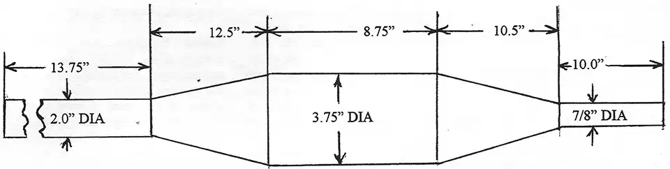
measured through center line of pipe.
by Bobby Lucas
Originally printed in 2000 issue #7of Still….Keeping Track
The following information is for the type 51 (125), 52 (175), 54 (250), and 55 (400) motors. Special care should be taken to clean the motor thoroughly of any dirt and grease before attempting to pull it apart.
The KTM powered Penton motorcycles are without doubt one of the most reliable if not the most reliable 2 stroke engines of all time. Restoration of these engines is going to be either very easy or very difficult based on the condition of the project motor.
Magnesium is a product that is very light and very strong, however, once exposed to the outside elements for a long period of time, moisture can cause corrosion inside your engine crank housing. Tolerances on KTMs are so close that many engines that I start to rebuild are locked up and the crank and piston are frozen in the cylinder and cases. If I come across one with a frozen crank and or piston, this is what I do: Remove the clutch case cover. The KTM engines have a crank case drain plug which I use along with a parts washer to flush out the crankcase. Soak the engine and use a socket on the pinion nut to rotate the crank. Usually only a small amount of movement can be achieved. Work slowly and you may free the crank. Your piston may also be stuck in the cylinder. My trick here is to remove the head then the case studs. Rotate the cylinder in a clockwise counterclockwise motion, again easy does it and with ti me you can usually work the piston free from the cylinder. (If the piston is rusted solid to the cylinder, split the cases and remove the crank assembly with the piston still in the cylinder. The piston can then be removed with a press.)
Follow the Penton Service Manual for all the proper steps in your engine overhaul. Care should always be taken when disassembling an engine and use of proper techniques and special tools should be the standard to follow.
Special tools are required to work on this engine type and using other tools and methods should only be done by someone who has lots of experience or spare parts to replace the ones you may destroy.
A 40 ton press is required to work on the crank and special holders for clutch basket and pinion gears are needed in disassembly and reassembly.
One tool that is required is the bearing puller for the crank bearings M20 and M25 and the bearing extractor for the pinion shaft bearing.
Split the cases once you have freed the crank. You may split the cases with the crank still frozen, but be very careful. One item which hinders case splitting is the driving shaft. It has a spacer which is between the sprocket and bearing. On most occasions tapping on the shaft will free the spacer and splitting the cases is much easier.
Once your engine is apart, check all case castings in the crank areas for corrosion and the two small port holes. These two holes are for lubricating the crank bearings. Make sure that they are not blocked with sludge or corrosion.
If your scope of work is not a total rebuild of your engine and only the crank demands work, there is no need to proceed any further into the transmission or clutch.
Measure your crank width before pressing it apart. In the case of a 400, measure the weights then remove them. Measure the crank journals and record all measurements. This is your target when reassembled.
Follow the directions in the Penton manual for KW axial play and record this information also. For correct dimensions always measure several times to insure accuracy.
Note: This only applies to the crankshaft 400 cc starting with motor no. 2809.
Starting with the above mentioned motor number, a crankshaft is installed in the 400 cc motor to which two damper rings are fastened by screwing. In case of such motors with this crankshaft, the motor casing is altered, too.
For spare part purposes, all 400 cc crankshafts are delivered with the threaded holes for damper rings (Spare Part No. 55.30.018.001).
Such crankshaft can be installed as usual in the old casings. For motors starting with motor no. 2809 this crankshaft has to be completed with the damper rings (Spare Part No. 55.30.032.000) and the respective countersunk screws M6x12 DIN 7971.
It is however necessary to glue the damper rings with OMNIFIT Type green 150 M and the countersunk screws with OMNIFIT Type red 80 M. It is also possible to apply the corresponding equivalent products of LOCTITE.
After the gluing process the crankshaft needs a resting time of about 24 hours enabling the adhesive to harden.
The ready crankshaft may be ordered under spare part number 55.30.018.101.
From Penton Manual
Crankcase pre-assembly
Remarks: As previously mentioned the ball race rings and ball cages of the main bearings must under no circumstances be mixed together.
Main bearings should only be renewed as sets, never singly.
Measuring of KW axial play
If you renew the crankcase or the main bearings, the axial play of the crankshaft is to be measured. This must also be done if only removing the outer ring from the casing.
Place the engine casing halves with the inside facing upwards and place the ball cages with inner race rings in appropriate outer race rings in the casing. With the depth gauge, measure the distance from the casing joint face to the bearing inner race surface.
Make a note of measurement results and measure the second crankcase half. Add together both measurements and add to this 0.2 mm for the gasket.
Measure the crankshaft at the bearing contact surfaces and also make a note of those measurements.
THE axial play, through different thickness of compensating shims between the crank web and the bearing inner race rings should be so arranged that there remains an axial play of about 0.03 - 0.05 mm.
Example:
| Left crankcase half | 27.48 mm | (1.0818) |
| Right crankcase half | +27.45 mm | (1.0807) |
| Gasket | +0.20 mm | (.0078) |
| Measurement in Crankcase | 55.13 mm | (2.1703) |
| Measurement of Crankshaft | -54.50 mm | (2.1456) |
| Existing axial play | 0.63 mm | (.0247) |
| Permitted axial play | -0.03 mm | (.0011) |
| Equalizing difference | 0.60 mm | (.0236) |
This difference on both sides of the crankshaft is adjusted by the compensating shims. If the axial play cannot be corrected with the same number (thickness) of compensating shims on both sides, then the larger number should be fitted on the clutch side. Press ball cages from the inner rings.
Before forcing on the inner race rings, in each case there is to be placed an intermediate plate between both crank webs. This intermediate plate must be large enough for support of both sides and thus the crank shaft clearly rests upon it (press on inner rings with inscription outside).
Never tighten the crankshaft with a crank shaft pin or on the frame in the vice and try to hit the bearing inner rings. In such a case the crank webs are squeezed together and the connecting rod bearing is damaged which means the crankshaft cannot be used. After pressing on the inner rings fit the ball cage on the crankshaft.
Fix left half casing in the clamping frame; oil the retaining rings and introduce the crankshaft. Fit the gasket and fix the right half casing with screws. Rotate the crankshaft. Check with dial gauge for lateral wobble at crankshaft ends. This must not exceed 0.05 mm on the driving as well as the magneto side. Measure the axial clearance of the crankshaft, holding a dial gauge against a crankshaft end. By pushing the crankshaft backwards and forwards several times it can be ascertained that it is free. If the axial play does not lie between 0.03 mm and 0.05 mm then the crankshaft must be dismantled and an inner ring is taken out by means of the inner ring extractor. Add or take away corresponding compensating washers.
by Bobby Lucas
Originally printed in 2000 issue #6 of Still….Keeping Track
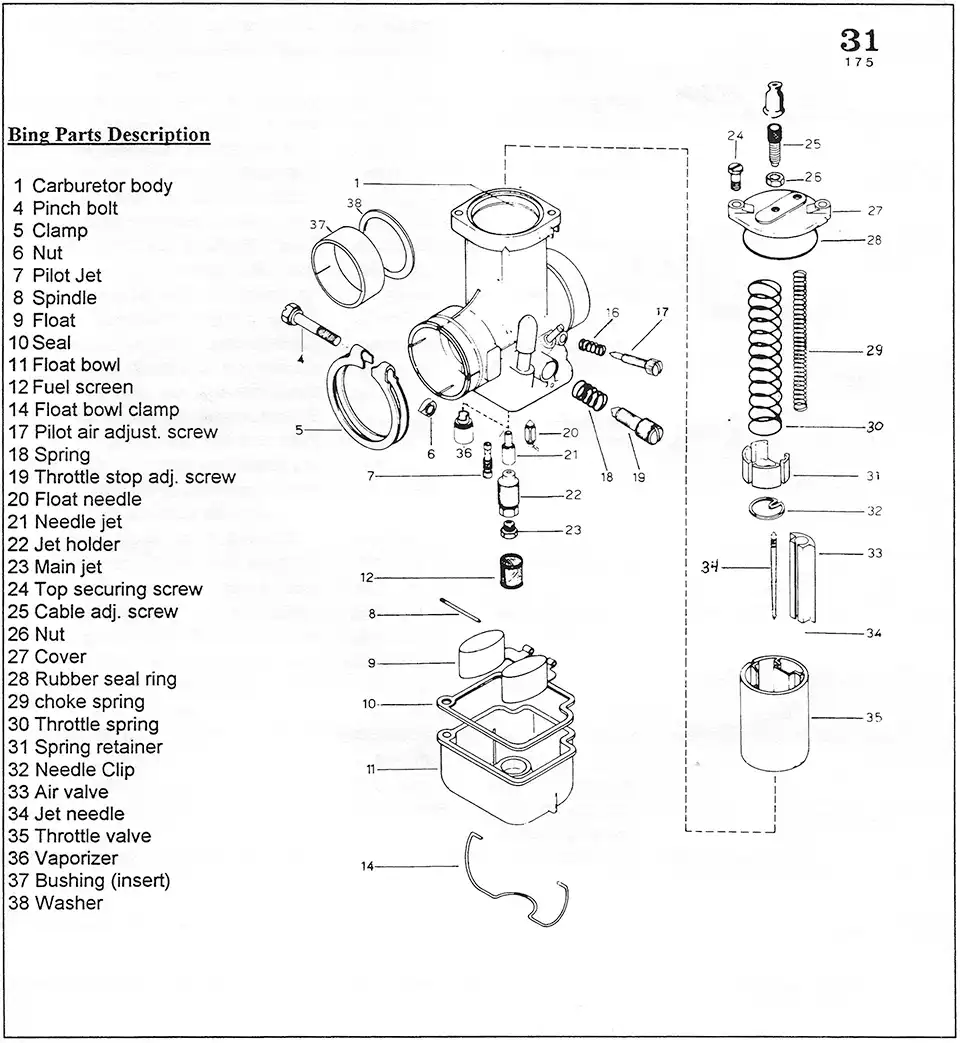
Penton motorcycles generally have a Bing carburetor mounted from the factory. When properly adjusted and maintained it will give the rider outstanding performance and reliability under all types of conditions!
Under the current vintage competition rules, the Lectron carb and other "flat slide" carburetors are not allowed. Early Jackpiners came with the Amal carb. However, in this article we will be talking only about the Bing carburetors.
The Bings mounted on 125s are 30 or 32mm and have the codes of 2/30/101. The 175s are 30 or 32mm and have the code of 2/30/102. The 250s are 36mm and are coded 2/36/102. The 400s are 38mm and are coded 2/38/102. The later model 125s and 175s had 34 or 36mm carbs and the 250s had 38mm carbs. The codes are stamped on the carb bodies.
The Bings mounted on the KTM powered Penton motorcycles were of two types. Type "one" were on all motorcycles up to 1976. Type "two" were mounted on Pentons in 1977 on through the life of this engine type. You can use a late model type "two" on an early model engine, but you must replace the intake manifold and rotate your air boot to fit. Your pipe will be very easy to remove when you change to the type "two".
Type "one" carbs were mounted in a couple of ways. On some the carb body mounted (clamped) directly to the manifold. The later types had a special insulating insert between the manifold and the carb to prevent wear due to engine vibration. Type "two" carbs were rubber mounted.
Carburetors are a fuel/air metering device which measure the amount of air entering a reciprocating engine and sprays into this air the correct amount of fuel for the desired condition of engine operation. The metering of the fuel to be mixed with air is the function of all carbs. Pressure is the key along with properly sized and adjusted components. Pressure is created by a good Piston. A worn piston may not provide the carburetor proper pressure to mix enough air and fuel causing a cold running (rich) engine.
Inspect your Bing in the following ways and you can use it a very long time. Check the carburetor mount for wear and any cracks at the clamp area. If your Bing is loose, trying to put six extra turns on the clamp screw & bolt, or using a larger bolt and nut will only cause you to crack your carb body. The manifold needs to be rebuilt ( or replaced) to the original dimension or the wear of the two parts compensated by the installation of an insert. If your carb is loose and it has an insert (#37), it (the insert) needs to be replaced.
Check your slide pin located on the inside wall of the carb body. I usually RTV it to prevent any movement of the pin and to prevent any air leakage through the outside part of the pin area. Remember, if air can get in , dirt and water can too.
Check your cable adjusters (#25) on the cap of the carb. Replace any worn parts. Check your tap screws on the cable adjusters for stripped threads or worn flats (from the cable). Replace your rubber o-ring washer (#28) on the cap. Never ride without it.
Check your slide spring (#30) for wear. A worn spring is one that is weak. Don't stretch this spring ever! Check your choke cable adjusters (#25) and spring (#29). Replace any worn parts.
Caution: never over tighten any of the adjusters on the cap
Check your spring retainer. I like the plastic retainer (#31) (part #51- 31-131-000 / or Bing #26-511 for the 175s and part# 55-31-131-000 I or Bing #26-512 for the 250s). This plastic retainer is very important. Never leave it out or your throttle cable will slip off the slide and you will not be happy when out riding. Early Bings had a metal flat washer and if you can, replace it with the plastic type.
Next, check your jet needle (#34) and the needle clip (#32) for wear. I highly recommend replacing both. I am a victim of a cut needle which thankfully fell into the needle jet and not into the engine.
The throttle slide (#35) will be a great indicator of the type of performance you will be able to create. If your slide front is worn and pitted badly, you will need to replace it. On type "one" carbs, Bing (Agency) cannot replace the slide. On type "two" carbs, Bing (Agency) has new ones in stock.
A dirty filter, an engine loose in its mounts, and an engine that is vibrating will wear the slide, needle, and needle jet to a point that a rich mixture is all you will get. Remember, keep it clean and tight.
Needle jets (#21) are made of brass and the needle is of steel. The up and down movement and the pressure from your cylinder will cause your needle to wear out your needle jet. You can tell the wear by looking at the small end (top) of the needle jet. An egg shape center means you need to replace the needle jet. Replace it ·with the same size or buy a smaller one and drill it to the original size.
Vaporizers (#36) (or mixing devices) need to be checked for wear or chips. I've seen some that are gone and the engine really will run rich.
Tickler assemblies should be checked to see if the clip holding the tickler in the body is worn or about to slip off Replacements are easily had. I've reached down and tickled the carb and let the tickler go only to see it shoot out of the carb. Not a good thing on the starting line!
Float needles (#20) should be replaced if worn. A ring around the top of the needle point will mean you need to replace it. Use only the same type of needle. If a wire clip is used to attach it to the float, always use it again.
Screens (#12) are provided in Bing carbs for dirt riding use. It is to keep fuel from surging into the engme while riding on rough terrain.
Bowl gaskets (#10) should always be replaced at overhaul time or if they are torn.
By the information provided in the Penton Operation and Maintenance manual and by some of the pointers I have given you in this article, you should have a smooth running, easy starting, reliable motorcycle. See ya at the starting line.
by Kip Kern
Originally printed in 1999 issue #5 of Still....Keeping Track
Al Buehner asked me to submit an article on the adjustment of Sachs 5 + 6 speed transmissions. What I wish to do is not quote "word for word" steps involved from shop manuals, but give some very important areas, I feel, to pay attention to when performing this task. By no means am I a professional, good common sense and a little reading can produce great results!
Step 1. Have a Sachs engine manual handy be it a Penton shop manual, Sachs repair instruction No. 336.8 E/4, or a Clymer service handbook M427. Follow the printed steps and you will be fine.
Step 2. Very good "things" to know!
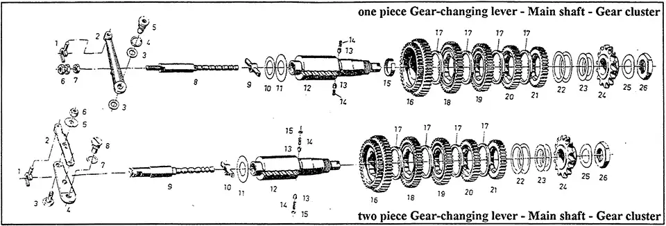
A. There are two types of gear selectors, a one piece, and a two piece. Adjustment procedures are different. Read carefully about the type of selector you will be adjusting.
B. I don't believe in the gear lock device; therefore, I don't use them, sorry!
C. Very Important! Before you can properly adjust any Sachs transmission, you must ensure the following:
- The main shaft (fig. 12) is shimmed properly between case halves.
- The shift key (fig. 9) is in excellent condition.
- The selector rod (fig. 8 & 9) is not worn.
- The selector rod detent cups and springs (fig. 13 & 14) are in excellent condition.
- The transmission gears are spaced properly and are not worn on the inside.
- The two springs on the shift boss are OK and that each flex properly.
- The shift boss is shimmed properly from the inside of the clutch case.
- The space between the shift boss and the clutch cover is shimmed properly, prior to placement of the clutch assembly.
- Properly shim the shift arm pivot point in the case.
- Use an unworn shift fork (fig. 1).
D. Don't worry about the stop bushing, eccentric cams, whatever, until transmission adjustment is complete.
E. Statically adjust the shift arms per instructions, rotate main shaft and run the transmission through the paces. If it shifts OK from 1-5 or 6, you have it! If not, adjust the arm to meet direction needed, i.e., 1 piece arm = rotate selector arm fork nut (fig. 6) in or out to achieve adjustment. 2 piece arm = turn eccentric screw on arm (fig. 3) to achieve adjustment. In either case you must be able to rotate the main shaft and run the shifting through all of the gears. Once done, shift to lowest gear, hold down on the shifter and adjust the cam stop and tighten. Next, shift to highest gear, hold up on the shift lever and adjust the cam stop and tighten. Now, after all is adjusted and checked tight, statically run the transmission through all of the gears again and ensure that it shifts OK from top to bottom. With luck, you won't have to readjust and you will be finished!
F. Handy tools to have to adjust transmissions:
- For 1 Piece arm= Depth Micrometer for .910-.915 measurement
- For 2 Piece arm= "thin" 13 and 10mm wrenches
As you can see from the above comments and your reading of the shop manuals, this is an easy task but always remember it is imperative that this engine and transmission be shimmed properly to function correctly!
by Bobby Lucas
Originally printed in 1999 issue #4 of Still....Keeping Track
Boy, one could write volumes on this subject alone but we will try to help the rider as much as possible here.
First you must identify which clutch system and motor you have. Hopefully your clutch is complete. Early clutches were made of brass and steel. Adjusted and maintained, it will last a couple of racing seasons. This is our goal!
Penton/KTM 125, 175, 250, & 400's throughout the years, all used different kinds and numbers of clutch plates and related parts. Check the table at the end of this article for help and check your parts manual before ordering parts or reassembling. Because of the number of these changes, generally no one way is correct.
My past experience is that engines left at rest for many years need only cleaning and inspection of parts. Pay close attention to your pressure plate, to the spring nuts, and bolts. Count the number of threads showing on the eight spring bolts as this applies pressure to the clutch and will be an area of adjustment at a later time.
Every Penton owner wants to ride A.S.A.P. and often the bike will start and run, but the bike dies or jumps and dies when the bike is put into gear. Draining the crank case and filling it with new oil helps sometimes. Warm up the engine, drain the oil, refill, and try again.
One should really examine the whole bike before riding. This is a pre run check. Use common sense. Check brake cams, cables, crank seals, and the crank bearings. Clean the ignition, air box, and carb. I'll stop about all this, it's really an article by itself1 NOTE: Clutch drag, more often than not is caused by worn clutch push rods and the 6mm ball bearing, or the pin at the cam. Holding the bike in gear with the engine running for extended periods causes the two rods and the ball to wear or worse, causes the pressure plate, rods, and ball to become one.
Working on your clutch is easy once you have some tips. First off, determine what is wrong. A slipping clutch is one without enough pressure. A 1/2 turn on the eight nuts can solve slipping, if the plates are worn. You can check your cable to see if it's properly adjusted at the engine and handlebar adjusters. You may need a new cable. If your cable checks out, one or all of your disengaging parts may need replacement.
Normally I've seen the 6mm ball flat on two sides and the rods pitted. Replace the ball and check again. If it works, your batting a thousand. If not, you can clean up the action by placing 2 6mm balls in the center and grind off each end of the rods to the appropriate amount. This is a grind and fit method. Don't take off too much!
The bearing cover and it's disengaging lever may be so worn that only a replacement will do. Buy all the spare parts and bikes you can. Use the late model clutch set-up if you can find it.
NOTE: Late model set-ups are easy to see on some engines. Look at the clutch engaging housing (bearing plate assy). The advantages are that your disengaging shaft rides in a steel sleeve vs the old type where your disengaging shaft rides on the case housing. The housing is soft and if not kept clean and greased, will cause severe wear, and improper clutch action is the result.
In 1976 and up, all engines used a single rod with the bearings on either the pressure plate (housing is old style) or bearings on the housing end of the rod with a cup type bearing activated by a pin via the disengaging shaft.
The fibre clutch plates are directional and must be installed so oil will sling out of the basket when you open your clutch.
Clutch engine cases also allow oil to leave the clutch at a better rate on late model clutches. Early silver motors had only one flute, later models have two. Original silver covers have none and could cause some clutch drag. Original black covers are cool to look at but hold so much oil that a slow action is almost always going to happen if every part isn't in top shape.
If you decide to mix a late model clutch to an early model case, use all the parts from the late model to include basket and pinion gear. Believe it or not, they are a matched set. Use a 250 on a 250, 400 on a 400 as the number of teeth match the transmission gears.
My price list dated 1975 prices the disengaging cover complete at $16.60. Now I'm sure it's going to cost you 5 times that today to buy a new one or about the same to have one rebuilt. Jack Penton asked me what we should do to rebuild them and it looks like we can if they aren't too far gone. I've got a large supply of bikes, so I've never rebuilt one, but my machinist says we can. You need to be able to fit all parts and if rebuilt, you can make the proper adjustments.
CLUTCH ADJUSTMENTS
As stated earlier, pay close attention to the eight nuts and spring bolts before you take . apart your clutch. You should know that the only time it is required to disassemble your clutch is when a repair into it is necessary. You may replace trans1mss1on gears and crank parts without taking your clutch apart. I always replace the two bearings #Din 625-16005-C SV41 when I intend to race the engine. This gives you a true running clutch on the main gear shaft.
Once you have tested gear shifting through all gears you are ready to assemble your clutch. Usually I install the cases in the frame at this point of a restoration. Install your cylinder and head, don't forget to drill your piston. Now assemble your clutch (see table and manuals for sequence of plates per your engine type).
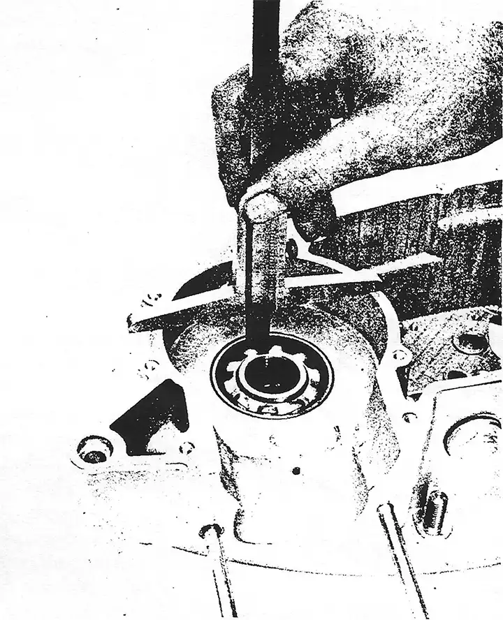
Tighten the spring bolts in a crossing manner so as to keep pressure the same. You need to make a tool to use here. Use a 10mm deep socket and weld a large nut or wheel to the ratchet end, leaving a hole large enough to lip a screw driver through so you can hold the bolts and tum the nuts. This would be the same as the special tool #51-12-006-000.
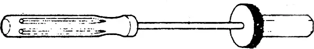
NOTE: screwdriver end must fit the inside of clutch nut's center (see photo below)
Once you have your clutch plates installed, install the rods and bearing from the bearing cover side , always grease with molykotle paste, tighten nuts and bolts and check your distance measurement of the disengagement lever on the bearing plate - late models 44.5 to 45.5mm, early models 42.5 to 43.5mm (see photo below).
NOTE: Rounded end of the rod goes in first, then the 6mm ball, then the second rod, flat both ends.
Disengage the clutch and check the pressure plate to see that it lifts evenly. Install your clutch cable and adjust it to a good feel. Install your drive sprocket, chain, and rear wheel if they have not been installed already.
Take out your spark plug. Shift your transmission into a low gear. Pull your clutch lever to the handlebar and check that you have 1/2 inch off the bar and zip tie it in that position. Place your bike on a center stand (crate) and tum the rear wheel and observe the pressure plate. It must be true at all springs, nuts, and bolts or a hot spot in the clutch plates will occur and uneven wear of the plates will result. You may also set up a dial indicator to true the pressure plate.
Align the nuts on the clutch with the hole in the bolts in such a way that you can wire all eight nuts together in a circle using . 040 steel wire or use the stock pins size lxl5mm.
Cut your zip tie at the handle bar, install your kick starter, replace your spark plug and shift the bike back into neutral. With the kick starter, push the engine through. If your compression is up (new top end we hope) and the motor turns over, your in great shape.
FINAL TEST
Fill the transmission with oil and go for a ride. Some adjustment of the clutch cable may still be required, but not usually. The final test is under power and with clean solid shifts. The last test is to see if you can easily find neutral with the engine hot.
Now go win some races!
INSTALLATION SEQUENCE OF CLUTCH DISCS
To include Late 79 to 81 KTM's
Late Model clutches
125 - 175cc Beginning with an organic disc, you have to put in alternating 5 organic and 5 aluminum discs
250cc Enduro - Beginning with bottom ring, put in first steel disc and then alternating 7 sinter and 7 steel discs.
250cc MC - Beginning with 2 steel discs,
400cc - First put in the bottom ring, begin with the steel disc and alternate with 9 steel and 8 fibre or sinter discs.
Early Model clutches ( 1972 thru 1977)
250cc Hare Scrambler - 8 steel, 7 brass, 1 steel ring
175cc Jack Piner - 6 steel, 5 fiber, 1 steel ring
Thickness of clutch plates
125, 175, 250 MC - Clutch disc, organic 3.5mm
250 Enduro - clutch discs 2.5mm
400 MC/ Enduro clutch discs 2mm
Length of clutch springs
1.5mm diam x 40.5mm - 175
1.6mm diam x 38.5mm - 250
1.7mm diam x 37mm - 400
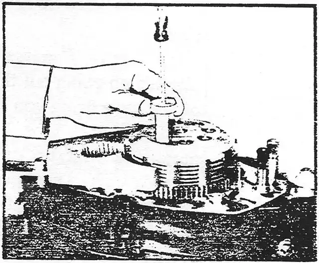
Photo showing how to use the special tool #51-12-06-000.
The screwdriver is used to keep the screws from turning. Turn the nut on the tool to tighten the clutch nuts till correct number of threads show, usually 3-4 threads
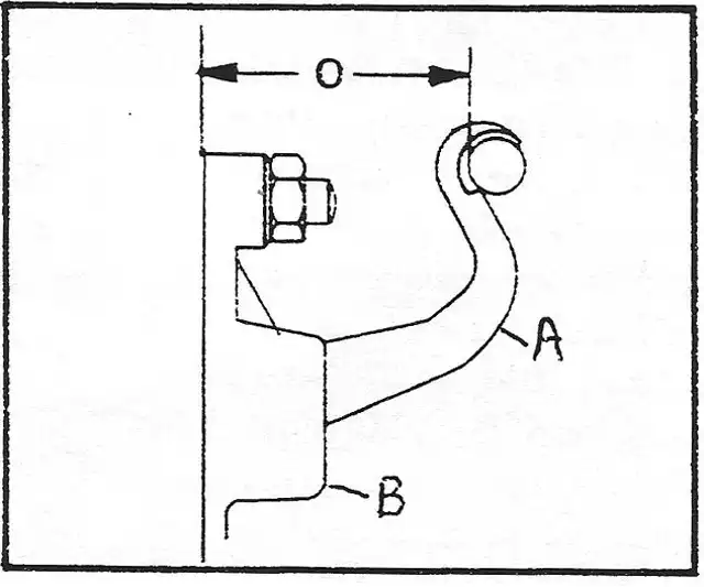
Photo showing the measurement of the disengagement lever (A) on the bearing plate (B)
LET'S DO IT RIGHT
by J. D. Slater
Reprinted November 1973 Keeping Track
NEW CARB SPECS FOR 175cc
Bing and Amal and 125cc 30mm Amal
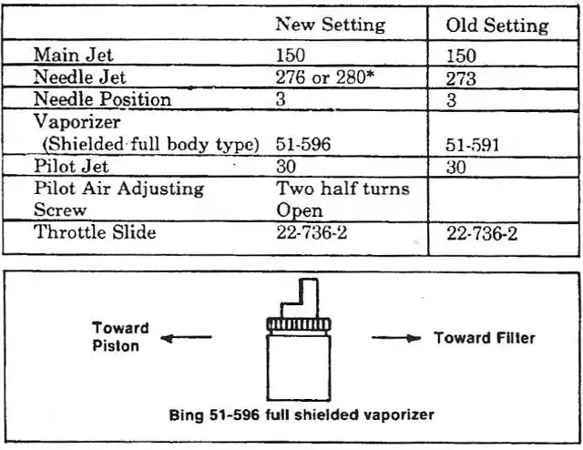
With our constant testing of the carburetor on the 175cc we have come up with what we feel to be the optimum set-up available now. This is for the Bing Garb on the Frame Breather models.
Some of the machines may have some or all of the correct settings so check it out before getting new parts.
The result is a higher needle position, a needle jet 276 and vaporizer 51-596. The vaporizer must be put in properly so that the shield is pointing to the air filter. If it is installed in the wiong position the carb will not operate properly.
*Tests show that in some altitude areas you may still experience a little pinging in the mid range. If so, we suggest using a 280 needle jet and dropping the needle all the way to the first notch.
30mm AMAL CARB SET-UP
If you have an Amal on your 175cc or a 30mm Amal Conversion on your 125cc we have also brought these specs up to date.
175cc PENTON WITH 30mm AMAL
Size 30 Pilot Jet
Size 260 Main Jet
Size 106 Low Orifice Needle Jet (*updated)
#2 Long Needle to Match
#4 Slide
Pilot Air Screw ¾ turn out
Needle starting in all the way down position. You can also update the Amal if it isn't already with a plastic float bowl, nylon tipped float needle and a tickler conversion. You may find all or many of these things done to your carb already.
For the 125cc 30mm AMAL CONVERRSION
Size 20 Pilot Jet
Size 240 Main Jet
Size 106 Low Orifice Needle Jet (*updated)
#2 Long Needle
#4 Slide
Pilot Air Screw ¾ turn out.
Needle starting in about middle position.
The major note to make and remember is the air adjusting screw and setting on the Ama l carb. CAUTION! The air adjustment screw is very, very, very delicate in setting. The slightest little movement on the screw will affect the engine throttling in the most major way.
This is ninety percent of what you need to know about the Amal carb and if you don't know this, you will think as Dirt Bike Magazine that they are junk carburetors.
Remember! Screwing in the air jet is giving it more gas and less air. When starting the air adjustment, start with air screw ½ to ¾ turn open. After you have this air screw set, then 3M the screw so no one screws with it.
If the carb ever acts up, then nine times out of ten, the pilot jet is plugged. If so. remove the air adjusting screw, pull gas line off of bottom of carband blow in the air screw hole with air pressure nozzle. Put air screw back in, gas line on, and readjust air screw.
We have found with proper installations, settings and operation that the Amal carburetor gives as good as or higher performance than any other two stroke carb in the world torlay. Evidence of this statement is that a major portion of the European Grand Prix Motocross machines use Amal and the entire Zundapp six Days entry has used Amal carburetors.
The problems with Amal for two strokes have always been that these Amal people have never had two stroke service representation here in the states. I always make mention of the British Amal, not the Spanish Amal. The Spanish have had service representation and enjoy a good reputation.
We now have available a 30mm Amal conversion for the 125cc Penton. We have found this carb to give improved performance and speed for the motocross rider. The kit #1002 consists of a 30mm Amal carb, (properly set-up), manifold adaptor, quick throttle, cables and choke lever along with tuning instructions. They should be available at your local dealers now or very soon.