Sachs A & B Motors
What's The Difference?
by Alan Buehner
Originally printed in the 2004 issue #23 of Still….Keeping Track
The Penton motorcycles from 1968 thru 1975 were equipped with 100cc and 125cc Sachs motors. Since the 100 and 125's used the same bottom end they could easily be switched over by changing the piston, cylinder and head.
The early Sachs motors (from 1967 thru 1971) were classified as the "A" motors which came with a large diameter crank and thin selector rod with a 8mm selector key. Because of problems with over shifting and not being able to adjust the shifting mechanism, the motor was updated around 1970.
The "B" version was equipped with a smaller diameter crank and a thicker selector rod with a 10mm selector key. All Sachs motors came 'With a serial number I.D. Tag which was riveted to the top part of the ignition cover. However, because all ignition covers are interchangeable and the ignition covers were subject to damage if a chain was thrown, you cannot go by the the LD. tag to identify which version motor that you have.
The following photos show the differences.
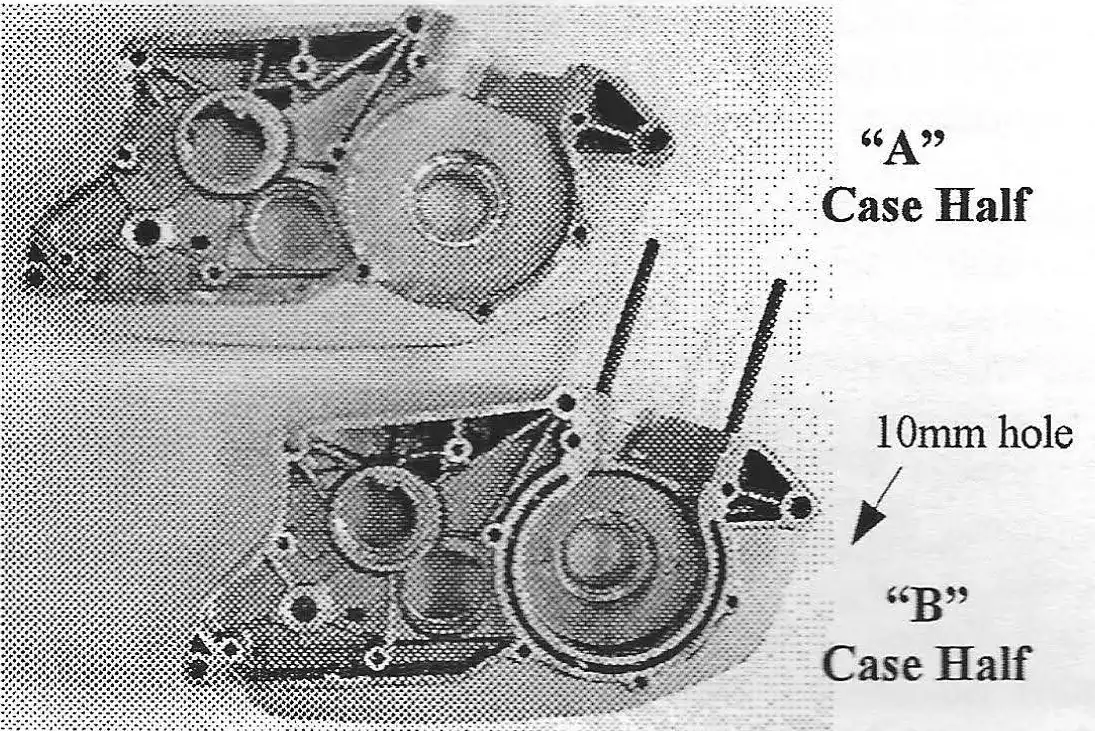
MOTOR CASES
The top motor case is an "A"motor with a 8" diameter crank opening.
The lower motor case is a "B" with a 7" diameter crank opening. Note the double w,ill around the crank area. Also, the opening in each is deeper to hold the thicker crank.
NOTE: Check the front mounting hole. Early "A" motors have an 8mm hole. Some "A"s and all "B"s have a 10mm hole.
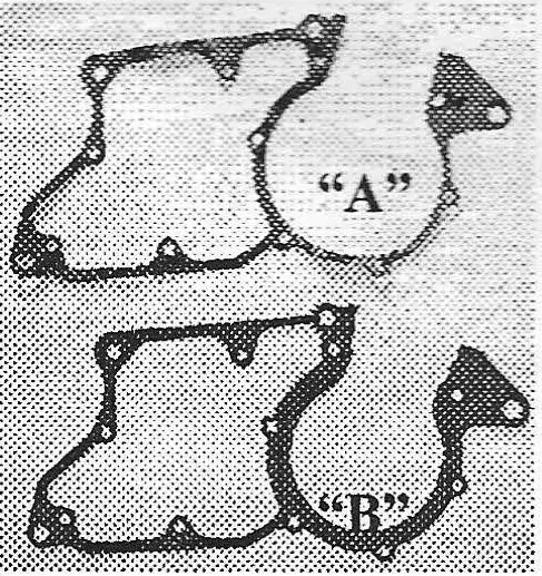
The difference between the "A" and "B" motor cases is obvious when you see the center case gaskets. The "B" center case gasket is thicker around the crank area to match the double wall construction.
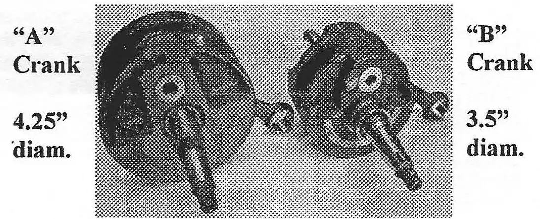
THE CRANKS
The "A" crank (left) is larger in diameter than the "B" crank (shown on right). Some "A" cranks came equipped with aluminum rods, however both can use the same steel rod with the only difference being the length of the lower pin. Both cranks use the same size M-20 crank bearings.
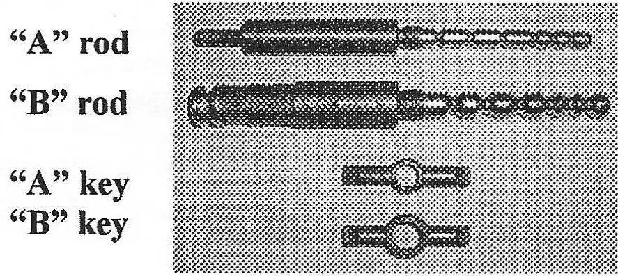
SELECTOR RODS AND KEYS
The "A" selector rods are thin in diameter and have a threaded end for attaching the shift linkage. When compared to the "B" selector rod, you can see the problem the early"A" motors had with over-shifting because of the smaller grooves for the pins to catch.
The selector keys as shown are not interchangable because of the difference in diameter.
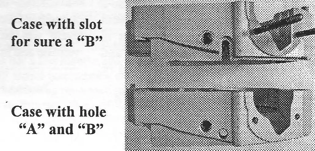
IGNITION WIRING
There is only one way to identify a "B" motor case without having to split the cases, and that is by the cast slit in the case to route the Motoplat ignition wiring (see top motor case in photo). The "A" motors came equipped with Bosch points and condenser ignitions and it's loose individual wires were routed through a round rubber grommet through the round hole in the motor case as shown. Because Sachs built their motors to accommodate the bike builders, there are several versions of cases. There are "B" cases with round ignition wiring holes! Some motors were still being equipped with the Bosch ignitions even though the Motoplats were available.
What's The Difference?
by Alan Buehner
Originally printed in the 2004 issue #22 of Still….Keeping Track
The Penton/ KTM motorcycles were equipped with the best front forks available at the time. As time went on, technology changed and improvements were made primarily in the length of fork travel. As these changes were made, they were included on the latest model bikes being sold at the time.
As a result of the changes made over the 10 year life of the Penton motorcycles, there are a variety of different styles and a couple of different brands that were used. Unless you have a garage full of Penton bikes, you , would have no idea of what to look for. This article is being written for our members who only have one or two different if models of bikes to help them identify a Marzocchi from a Cerianni and a 32mm from a 35mm.
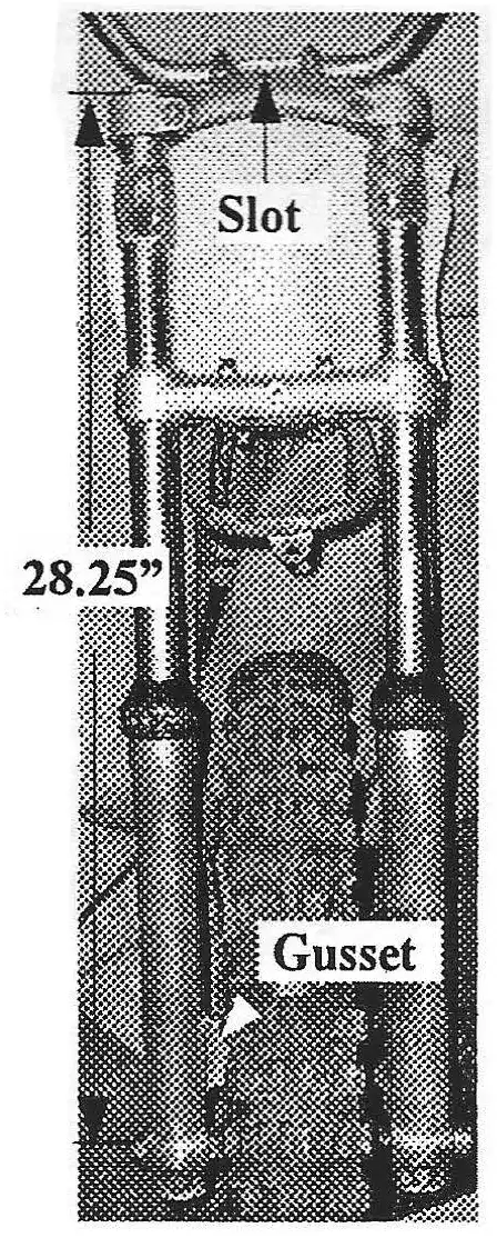
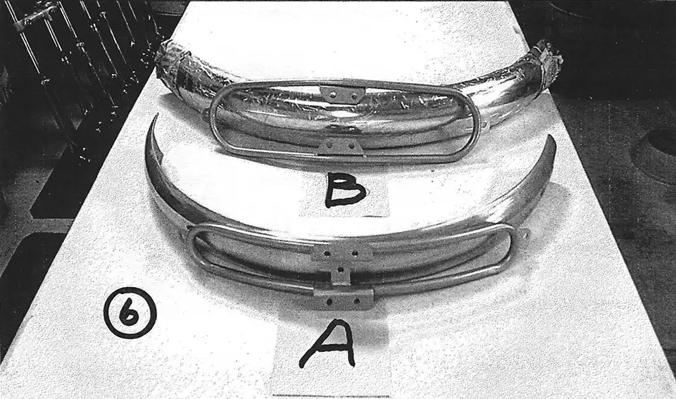
From 1968 thru 1971 the steel tank Penton motorcycles came equipped with 35mm Ceriani forks. These are easily identified by 3 visible features. The first is the rectangular shaped gusset sticking out on the side of the right fork leg. This gusset fits into the slot of the backing plate of the front brake. The second feature is found on the top fork plate. It has a rounded slot formed in it, that the bottom part of the handlebars fit in. The third feature is the top of the fork tubes, 35mm Cerianni which is squared off (there is no taper). Another feature is the top of the fork legs. The fork boots slide down over the leg and are held in place with a clamp.
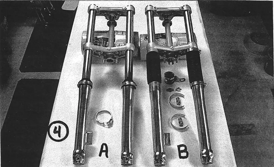
The 1972-73 Pentons were equipped with 32mm Cerianni forks. There were 2 styles, the narrow version (A), and the regular version (B).
The narrow version is identified by the single alien head bolts on the fork plates that pinch each fork leg. These bolts are visible on the front side of the fork plates.
The regular version is identified by the double allen head screws on the fork plates. These are visible on the sides of the fork plates.
The 32mm forks are both easily identified by the drilled and tapped round gussets on the front and back side of each fork leg to which a fork brace can be bolted to.
The 35mm Cerianni forks were installed on the 1973 Penton Hare Scramblers. In 1974 they came as standard equipment on all of the Penton motorcycles.
This newer version of the 35mm Cerianni is easily identified by the rounded, tapered sides of the fork plates that circle the fork tubes.
The top of the fork tubes are tapered. This matches the taper on the top fork plates. There are no pinch bolts used on the top fork plate to secure the fork tubes. The tubes are locked in place with the fork tube nuts which are in the shape of an oversize hex head.
The lower fork plate has one allen head bolt to pinch each fork leg. These two bolts are located on the back side of the fork plate.
The top part of each fork leg has a groove in it into which the fork boot snaps, eliminating the need for clamps.
In 1976 the leading axle forks were introduced on the MC 5 model Penton motorcycles. These were the 35mm Cerianni brand forks which were switched over to the Marzocchi brand forks by ,1977 at which time they were installed on all the bikes sold.
Cerianni leading axle forks are easily identified by the large oversized hex head nuts on the bottom of the fork legs. Another identifying mark is the fork tube nut which is shaped into a hex nut for removal with a wrench.
The Marzocchi fork legs bottoms are not threaded and do not have a hex nut. The bottom of each fork leg is not round all the way around and each one has a flat spot on the inside and outside part at the bottom, below the axle.
Another identifying mark is the fork tube caps which have an alien head slot in the center. An 8mm allen wrench is needed to remove these.
D - 35mm Marzocchi fork
have large hex head cap nuts.
by Alan Buehner
Originally printed in the 2003 issue #21 of Still….Keeping Track
res-to-ra-tion 1. The act of restoring a person or thing to a former place or condition. 2. The bringing back of a building or work of art as nearly as may be to its original state; also, the restored building or object.
pre-serve 1. To keep in safety; protect from destruction, loss, death, or detriment. 2. To keep intact or unimpaired; maintain. 3. To keep from decomposition or change.
At last year’s “Penton Day at the AMA”, Mark Mederski, Director of the AMA Museum, pointed out three Harley Davidson motorcycles from the 30’s that were on display. One was a restoration, with bright chrome and shiny new paint. The second bike was all new, built from the ground up with new old stock parts. The third was a used unrestored bike that had all of the original parts on it which was obvious with the dull chrome parts and faded painted parts.
Mark pointed out that the third bike was the more valuable of the three because of it’s “original” condition. It was a historically correct example of what that particular model bike looked like. The paint colors are correct and all nuts, bolts, and body parts are intact and accurate. The unrestored bike also serves as a reference model for someone in need of restoring a bike to see what parts and colors are correct and needed for that bike to be accurate.
Mark explained that the three bikes were on display to show the difference between them. There is an argument going on in the collecting world as to: when do you restore and when do you not restore and just preserve a bike? The argument also extends to the value of restored vs. preserved bikes.
This argument extends also to the Penton motorcycles, however it is obvious, in my opinion, that preservation of an unrestored Penton will command the highest price. Yeah, beauty is in the eye of the beholder, but 80% or more of these bikes are in need of restoration if they haven’t been restored or modified already.
Let’s face the facts. These were dirt bikes, built for competition, not street bikes that were routinely washed and waxed once a week. They were purchased for off-road racing through mud, water, trees and rocks. They were built under John Penton’s specifications to be dependable. They were too dependable and as a result the average rider did not treat them like race bikes by performing the required maintenance after every use and just kept riding them until they finally broke or they were parked because a newer model bike was bought to stay competitive with the new innovations that came out every year.
Some of these “parked” bikes were rediscovered after a few years of sitting idle and were desecrated by new riders who continued riding them until they became beat to death because they did not know anything about maintenance, repair manuals, or where to buy spare parts. These are typically the bikes that we have been finding for the past ten or more years. The frames are all rusted, body parts are missing or busted, and the motors are worn out, broken, or torn apart.
During the past year I have received a few phone calls from some “new” Penton owners that had come into possession of that rare “like new” Penton motorcycle and are calling me for advice on paint colors and parts availability to restore their new found pride and joy. After asking them questions about the condition of these bikes I have to plead with them NOT to restore it. This is a tough argument to get across to most of you guys because shiny new paint does attract attention which goes hand in hand with pride of ownership.
The Penton brand of motorcycles are very collectable in the vintage dirt bike world. Placing a value on one of these depends on year, model, if it runs, and if it is all there. However, future value will also be based on the unrestored condition just like you see on the Antiques Road Show. Someone brings in some furniture and is shocked when they find out that by restoring it they devalued it by thousands of dollars.
“Like new” Penton motorcycles are still out there. They are the bikes that someone bought because their buddy bought one, they tried it and didn’t like it or got hurt, so they just parked it in their barn or garage and forgot about it. The crazy thing about these bikes is that if you discover one, the owner will just give it to you or sell it dirt cheap to get it out of their way.
Preservation is the way to go with bikes that have obvious signs of little or no use. I talked to Mark Mederski and he offered the following recommendations:
The first step is to clean the bike thoroughly with detergent and water.
Motor, nuts & bolts - clean with kerosene or mineral spirits. Apply with a spray bottle and brush.
Painted surfaces - clean with mineral spirits and a brush. Use lacquer thinner on a rag to clean up tight spots, like frame gusset joints. Scratches and chips can be repaired by applying touch up paint with a brush (do not use spray paint from a can). Use a retarder in the paint to slow the drying speed. Use a pure paste wax to seal and protect.
Upholstery - clean with a vinyl cleaner.
Chrome & Alloy - use super-super, fine bronze or brass wool to clean off oxide (check furniture refinishing suppliers for this) - do not use steel wool! Use a pure paste wax to protect finish.
Tires - clean with “Miracle Crystalline Wax”. Apply it with a clean scrub brush. It is a museum quality wax with neutral chemicals that seals the rubber against decomposition.
Note: Do not clear coat any parts on the bike. Stay away from using brake fluid as a cleaner. When in doubt, ask for information. Do not rush through the cleaning process - take your time and think it through. If your bike has stickers or decals on the gas tank and fenders, consider leaving them on - they are a representation of the time period and show that it was a race bike. Preston Petty fenders also represent the time period and can be cleaned and shined up with polishing compounds specially made for them.
Storage - make sure that all fuel is drained from tank and carburetor (today’s gasoline might contain some form of alcohol which attracts moisture). Exposed metal parts should be coated with a rust preventive such as “LPS-3”. Make sure that the motor is vented (tranny and ignition area) to prevent condensation build up. The motor can be drained of motor oil but inside should be coated with a rust preventive such as “LPS-3”.
by Alan Buehner
Originally printed in the 2003 issue #20 of Still….Keeping Track
This article is based on an article that was published by Cycle World in their August 1974 issue. It was written by John Wasser and was titled "PREPARING THE PENTON - Getting ready for the ISDT with the guys who know how." John visited Penton R & D to see what special things were being done to prepare the Penton bikes for the upcoming ISDT and interview the riders as they were working on their bikes. This should help our club members in preparing thier bikes for the upcoming ISDT Reunion Ride in October.
The article backs up the stories that I have heard from Doug Wilford and Paul Danik about their "factory" ISDT bikes. The bikes were essentially stock. In fact the bikes were ready to ride right out of the crate from the factory, but because of the demands of Six-day riding, everyone would tear down their bike just to double check everything. Also, riders would make personal modifications to areas of the bike where they encountered problems from previous rides. The only item that was installed on all of these bikes were the optional center stands which are needed on ISDT bikes.
Any changes or modifications made by the individual riders were done to make it easier and quicker to fix something. Doug Wilford would drill a hole in the carb float bowl, install a fitting and connect a long hose from it up to the handlebars. A fuel filter was installed halfway up the fuel line. If you should drop your bike, trying to restart it is hard because the carb bowl floods out and you have to sit and wait (with the throttle wide open after restarting) during which the motor blubbers and sputters before using up the excess fuel and starts to run crisp again. All Doug had to do in the same situation is suck on the tube at the handlebar (this draws the excess gas out of the carb float bowl) restart his bike and continue riding. Tom Penton had a similar set- up on his bike.
According to the article, Doug and Tom shared most of the innovated ideas.
Common things done to their bikes were welding gussets to the frame in areas that needed reinforcement and valve stem holes would be marked with fluorescent paint on the side of the rims to make it easy to identify during tire changes. Rear brake actuating arms were turned 180° and the brake rods bent around the rear shocks to prevent the braking mechanisms from getting damaged.
Most modifications to these ISDT bikes would eventually be made by the factory to future production bikes. Some riders are more proficient at doing things than others. According to the article, Carl Cranke was the team's expert wheel lacer. Carl wound up refacing most everyone's new DID rims. Dane Leimbach tested Motoplat lower units from stock to find the strongest running units. These were used in place of the units that came with the bike.
All of the KTM motors were pulled apart and new special made kickstarter shafts from Penton' s R&D were installed.
Air boxes were of the biggest concern for everyone. They were closely examined for any small cracks or pinholes. Epoxy, silicone sealer, and duct tape were the items used to seal up any leaks from the air boot up through the frame to the hi-breather intake.
Time is precious during an ISDT event and must be well spent. Teamwork, training, and proficiency are stressed upon the riders. Things like changing a tire are performed the same way by everyone on the team.
It was also mentioned in the article that where some ISDT riders would be taking it easy prior to an ISDT event to prevent injury, the Penton team would ride other events right up to the start of the ISDT. Their philosophy was that you can get hurt anytime, anywhere.
It was mentioned in the article that the biggest factor in riding an ISDT event is support which included lubricants, tires, fuel, refreshments and personnel. Penton would be providing this support for the entire Penton trophy team and the Italian trophy team who were also mounted on Penton/KTM bikes. Ted Penton was in charge of this operation. Individuals from club teams were also being extended this courtesy.
In my conversation with Paul Danik regarding this article, he said that he preferred to keep his bike prep simple and less exotic. He would make sure that every nut and bolt including the spokes received a coating of "never seize". His concern was to be able to tighten or adjust anything on the bike whenever needed during the Six-day and be able to do it easily. Spokes for example could be tightened without having to "crack" them loose.
All the riders would remove the rim bands and use duct tape to cover the spoke nipples. Also rim locks were never used. Paul took a cold chisel to make notches in his steel Radaelli rims. This would give the proper grip to prevent tire spin on the rim yet allow a faster tire change rather than fighting with the time consuming rim locks.
He would install spare cables on his bike and also take the time to hook them up and try them out to make sure that they fit and worked properly.
Paul's belief was if his bike in stock form was good enough for enduros and qualifiers, it was good enough to finish a six-day event.
After reassembling his bike, Paul made it a point to put at least a hundred miles of riding on it to break it in and make sure that everything was working as it should.
by John Durrill
Originally printed in the 2003 issue #18 of Still….Keeping Track
Two men (my son Peter and I); one motorcycle; lots of help.
It started with one 1973 Penton Six-Days and a desire for a motorcycle that would suit an old fat, out-of-shape enduro rider. Actually it just started as a winter project. A desire to have a Penton like "back when", a bike to run the ISDTR, and to ride in the woods at least once a month. We began gathering the bits and pieces to build a new 1973 125 Penton.
The frame was sandblasted and painted with PJ's KTM silver. An "A" 5-speed motor was built with a set of what we thought were NOS "A" cases. The area where the cylinder resides and transfer ports meet are much larger than a standard A or B engine. We still have not identified what the cases came from.
A trip to the Poteau Mountain Wilderness was enough to see that attacking inclines on a 125cc isn't quite as much fun as it used to be. We knew that we would need a replacement or some displacement for climbing more than sand banks.
Knowing that in the past, Penton sold "152cc conversion kits", we set about looking for parts and replacement parts (that was more of a decisive factor) to make an alloy barrel 152cc. Calls to our Penton parts vendors revealed that a stock of Wiseco pistons was available, but no replacement ring sets were available. Without a supplier for replacement rings, we started thinking bigger. We had a piston for the short cylinder (1977 and up) 175 to compare with a 125 piston. The height from the wrist pin to the top outer edge of the piston was the same. The Penton 175 used the same stroke as the Sachs 125. It looked like it would work, as long as we did not try to go larger than 1st over before replacing the custom liner that we would have to make. Machining out the stock Sachs "B" aluminum cylinder as wide as it could be bored and have a liner machined to fit would leave us with a very thin liner.
We ordered a standard and 1st over piston. While we were waiting on their arrival we received an e-mail from an internet friend in Holland. He told us that their team used Monarchs with 175 KTM top ends in the 70's to win gold in the SixDays. It took me only ten minutes on the phone to locate a cylinder head and pipe for the 77 top end ( chuckle, chuckle).
The cylinders have the same bolt pattern, so the 175 cylinder slid almost all the way down into the case opening. Normal "A" or "B" series Sachs cases will have to have the case opening machined out to fit the 175cc liner. The inlet to the transfer ports did not line up well. Due to a lack of gasket sealing area, we had to find a local welder who could weld the rear cylinder to fill in the crankcase/ gasket sealing surface on the back edge of the cylinder transfer ports. To get the cylinder all the way into the cases, the liner had to be removed and shortened at the bottom edge with a lathe. After the transfer ports were welded up, they had to be machined flush and the bottom of the cylinder lapped to provide a level sealing surface.
The crank was balanced by Falicon. The 175cc short piston was 1-1/2 ounces heavier than a 125 piston. So some attention had to be paid to the crank balance. Based on the amount of metal actually removed, re-balancing the crank we had was not necessary. The crank was mounted with a new A-rod kit from Euro-Rods and a NOS KTM 175 63.5mm short piston.
The head we ended up using was from a 1972 to 75 175 motor. Due to differences in combustion chamber shape, we ended up with lower compression than what was standard on a 1977 and up 175.
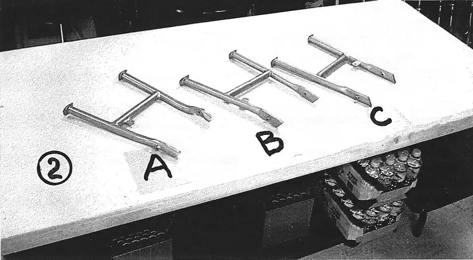
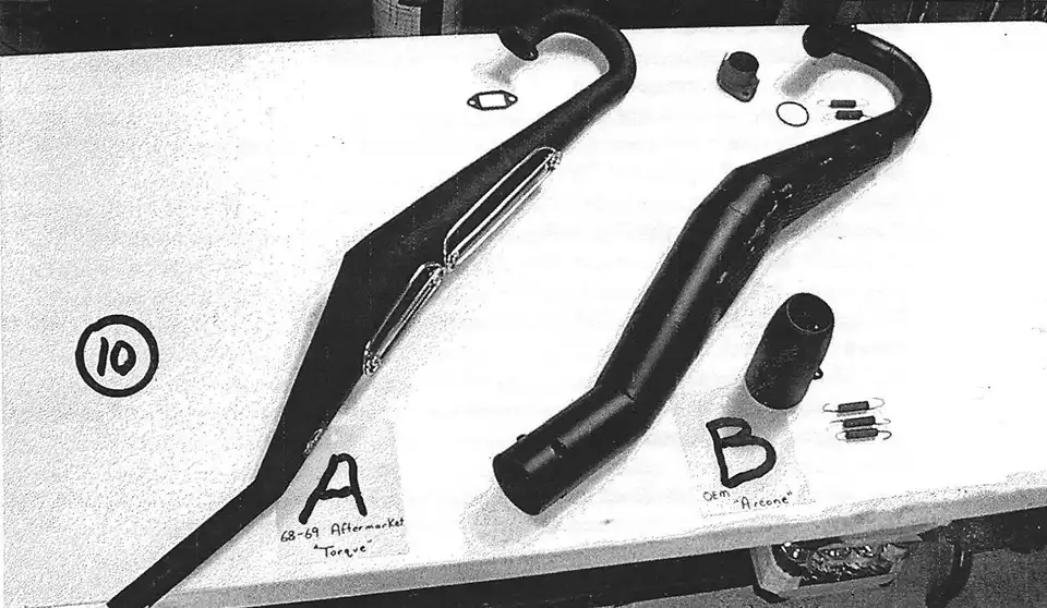
A 73-74 Jackpiner exhaust was massaged ever so slightly to fit in the 125 frame. A clamp-on SuperTrapp was welded to a stub replacing the stock stinger, silencer combo. A 2 inch stub of 3/4 EMT was used and a shroud fabricated out of muffler tubing from the local auto parts store. Then came the fun part, building a flange type intake manifold from an Amal intake and some sheets of aluminum plate. A few whacks with the hammer to the pipe, and the carburetor fit under the pipe and above the cases.
Unknowingly, the five speed gearbox we chose provided some additional benefits with it's wider gears. We do not currently know how much stronger the five speed box is, but it was considered necessary for the 182cc version Monarchs used to run the 250 class in the ISDT.
Lots of like new and new old stock parts went into the bike to make it a fairly complete historical representation of a vintage enduro motorcycle. The blue fuel tank will be graced with a set of custom vinyl sticker that say "Six-days l75cc".
The next several weeks saw extensive testing. with different Lectron needle and power jet configurations. The Lectron carb had a few eccentricities in store as we learned what we know about tuning it. The SuperTrapp, Lectron carburetor and lowered compression came together to form a power characteristic that is smooth and spread evenly throughout the power band. The engine leaves the impression of having two power bands. The first is likened to a mild trail bike. The second is like a hot 125 "B" motor with a lot more torque.
We used a Bosch Magneto (points type) from a military 125 engine. We like it better than the Motoplat. Timing is set at 3mm BTDC.
At this point in time, we have about 100 miles on the engine. It has worked out so well, that we don't plan to change anything unless we find some weakness caused by the boost in torque. We built the bike as an every day trail machine. If it holds up as well as the 125's of old, one engine rebuild is good for at least 6,000 miles with just the replacement of one ring set.
The bike weighs about 200 lbs fueled, is not as fast as a 175 Piner by maybe 4 Hp, but is a dream to ride. Old, Fat, out of shape enduro riders can go faster on it than on a stock Piner (chuckle, chuckle).
We had the help of the Lord (we did a lot of praying at times (GRIN) and the folks on the four continents with this project. We could not have done it without the support and advice we received from the POG members, The Vinduro group, and the folks that are members of Hercules IG in Europe. Our many thanks to all of you.
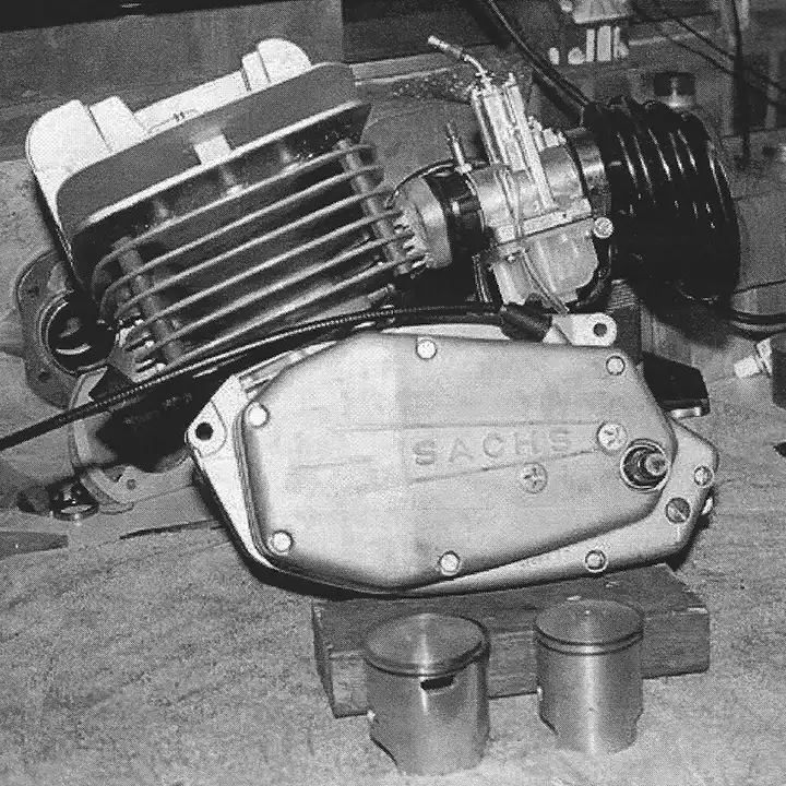
NOTE: cylinder is the shorter (6 fin) style made by KTM.
NOTE: carb bowl on Lectron is newest style that is opaque colored (not clear) which is alcohol proof.
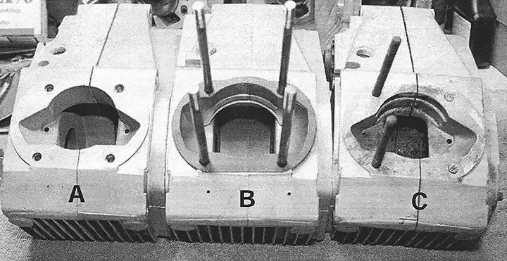
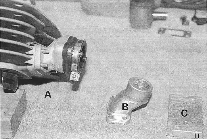
(B) Modified Sachs "B" motor case showing enlarged openings for transfer ports and bottom of larger cylinder sleeve. Longer cylinder studs have been installed
(C) Stock Sachs "B" motor case before modifications with two cylinder studs for 125 aluminum cylinder.
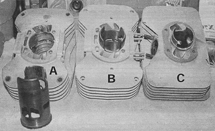
(B) Finished KTM 175 "short" cylinder with liner installed. NOTE: transfer ports on bottom of cylinder "A" were welded up to increase gasket area.
(C) Stock Sachs aluminum 125 cylinder.
(B) Stock KTM aluminum intake manifold before modifications.
(C) Aluminum plate, drilled with 2 holes for rubber carb mount, before being welded and shaped.
Parts and Accessories
by Kent Knudson
Originally printed in the 2002 issue #17 of Still….Keeping Track
Now that we've outlined both the engine (Part I) and chassis (Part II) set up, it's time to address all of the remaining components that were used to build the Pentons that Kevin Brown and Gary Roach rode to their AHRMA National Championships. As I stated in Part II, we have tried very hard to retain the original components and overall appearance of the Penton motorcycle. All of the following components (except the tank) are readily available and the only modifications made to them were for added reliability or ease of maintenance.
I would like to thank Alan Buehner, Karl Schneider, Larry Perkins, Barry Higgins of H & H KTM, Robbie Jenks of Athens Sport Cycles, James Giddings of Giddings Machine Racing and, of course, Kevin Brown and Gary Roach for their input and assistance with these components.
HANDLEBARS - We've had good luck with the Renthal #666 (seriously!) 6" motocross bar, which is the tallest off-road bar Renthal America imports. Renthal handlebars are made in the UK with very high quality aluminum alloy that is strong yet resilient in a crash. Kevin has crash tested these bars repeatedly and we' re still on our original set!
CONTROLS - I originally purchased Magura split perch lever assemblies and a Magura 312 "side pull" throttle assembly from H & H KTM, but Magura USA has since stopped importing the 312 throttle assembly. Your options include using the Magura 314 throttle assembly (same as the 312 but with a plastic housing) for around $20 or you can have your KTM dealer order the 312 (it was used on older KTM 4-strokes) for around $80!
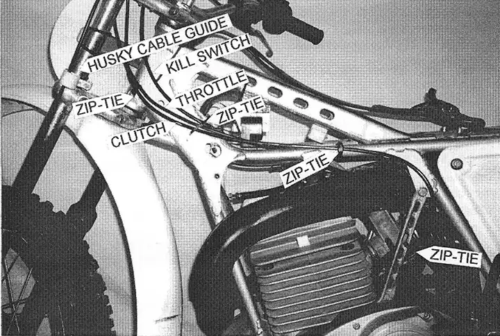
CABLES - The Terrycable clutch cable is from Alan Buehner and the Terrycable throttle cable that fits the Magura 312 throttle assembly and Bing Carburetor is from H & H KTM. The latest batch of Terrycable front brake cables has a funky adjustable clevis that I'm not too fond of, so I had Motion Pro make some front brake cables to my specs. I have also included a photo of our cable routing (see photo 1). I prefer to keep the cables loosely zip-tied to the bike at several locations to prevent excess movement or chafing.
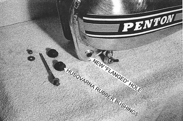
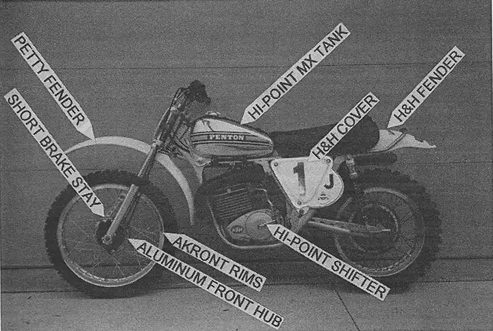
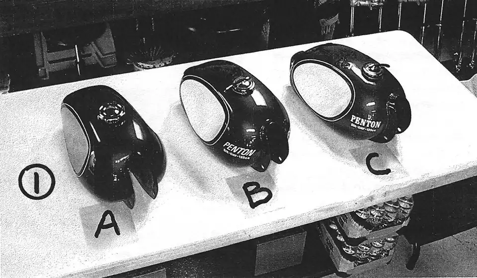
TANK - We use an original Hi-Point aluminum MX tank. The aluminum tank has proven to be very durable, as it dents but doesn't crack or break like the fiberglass tanks. It also eliminates any of the fuel compatibility issues some members have encountered with their fiberglass tanks. I heavily pad the underside of the tank at the front and rear to prevent any movement of the tank or contact with the frame. In conjunction with the leather strap, I also bolt the tank to the frame (ala Husqvarna) because we originally had trouble with the tank's mounting "ears" bending as the tank tried to move around during a race. To do this I first made a tool to punch a flanged hole in the tank. Then I used Husqvarna rubber tank bushings and a long 6mm bolt, washers and aircraft nut to hold the tank in place (see photo 2).
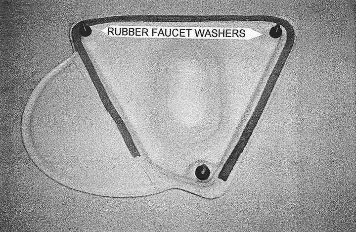
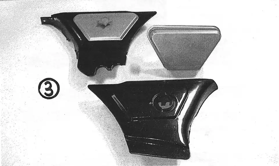
PLASTIC - The front fender is an original Preston Petty LB. (integral base) "Mudder", which is my favorite style of fender from the 70's. The side panels, rear fender, and front number plate are all sourced from H & H KTM. When installing the airbox cover, I push 2 hard rubber faucet washer over each bolt's threads between the cover and the airbox (see photo 3). These fill the extra space in the cover, allowing you to lightly torque the bolts without distorting the cover. They also fit tightly enough on the bolts to retain them to the cover during an air filter change.
I mount the right side panel with "studs" to allow for quick removal. At the front I use a bolt and locknut facing outward in the original mounting hole. At the rear I weld a stud to a large washer which I then place under the rubber exhaust mount.
The front number plate is bolted to one of Karl's stainless steel number plate brackets, which is available from Alan Buehner. Instead of one large o-ring, I use two 3" o-rings to hold the bracket to each fork leg in case of breakage.
SEAT - The seat is the 21" long, tall style built from scratch using Karl's fiberglass seat base, foam, and stainless steel brackets. The seat cover is from Alan Buehner.
FOOTPEGS - The footpegs are Karl's stainless steel cleated pegs, available from Alan Buehner. Because the footpeg mounting holes are typically worn oversize and the footpegs are loose, I drill both the footpeg and mount holes to 3/8" and use a new 3/8" bolt with a shank that is just long enough to fit through both sides of the footpeg. I also like the footpeg to angle upward slightly at the end so I have the welder build up the pad on the top of the footpeg mount and then I grind it to achieve the proper height/angle.
RIMS - We typically use the original Akront "mudcatchers" or original Sun rims. Buchanan's Spoke and Rim in Azusa, CA carries both Akront and Sun rims, as well as a ridged, Akront-looking Excel rim which they claim is stronger and less expensive than the Akront.
SPOKES - Buchanan's manufactures their own spokes, which are available in either steel or stainless steel. They also offer complete wheel building and restoration services if the thought of lacing your own wheels turns you off!
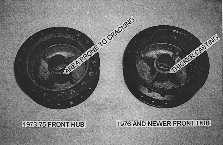
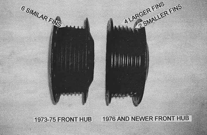
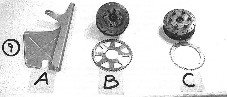
FRONT HUB - There are several options for front hubs and not all of them are good! The aluminum 1972 (and earlier) hub works great. The 1973-75 hub is identical to the earlier aluminum hub, but is cast from magnesium, which turned out to be a mistake. The thin wall section around the steel bearing sleeve worked well with the resilient aluminum, but ended up cracking frequently with the more brittle magnesium. By 1976, the factory rectified this problem by adding more material around the bearing sleeve (see photo 4) and brake lining. These hubs can be readily identified by looking at the fins (see photo 5). The 1973-75 hub has 6 fins of similar diameter while the 1976 hub has 4 fins that are noticeably larger than the other 2 fins.
FRONT BRAKES - The front brake shoes are Ferodo #FSB8 l 4 from H & H KTM. These shoes provide incredible stopping power from drum brakes! I also use the shorter 1975 brake stay, which rotates the hub slightly for better cable alignment (see photo 6), and a Husqvarna cable guide on the fork just above the bottom triple clamp (see photo 1).
At the 2001 ISDTRR, Kevin posted the 3rd fastest overall time in the acceleration/ deceleration test using this brake setup. First and second places were: Dick Burleson and Ray Mungenast on new KTM's!
REAR HUB - The magnesium hub works very well, hut is prone to cracking around the sprocket holes and spoke holes. Keep the spokes and sprocket bolts tight and be sure to check the areas visually before each race.
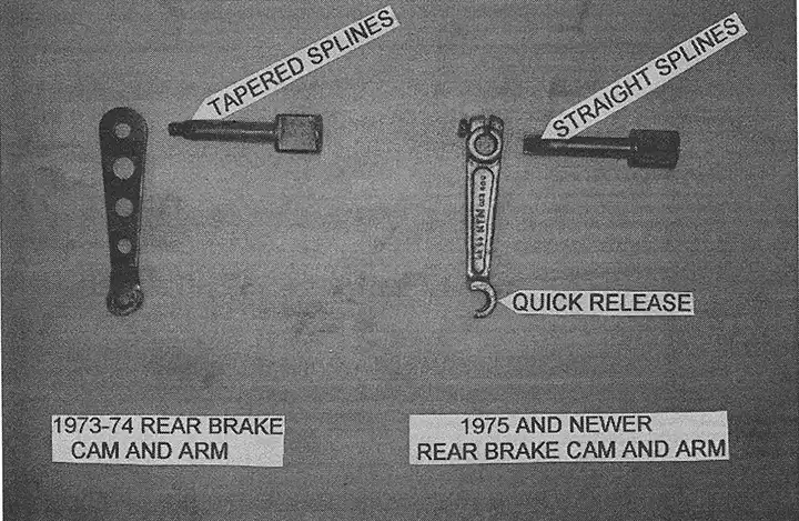
REAR BRAKES - The rear brake shoes are Ferodo #FSB815 from H & H KTM. I also prefer the 1975 (and newer) straight-splined brake cam and quick release brake arm over the 1973-74 conically-splined brake cam and arm (see photo 7). The final touch is one of Karl's brake rods and a steel Monark wingnut from Larry Perkins.
SPROCKETS AND CHAIN - We use a 14 tooth 520 PBI Pro steel front sprocket (#93-14), a 57 tooth 520 PBI aluminum rear sprocket (#5257-57) and a RK SXO 520 o-ring chain. This chain and sprocket combination lasts a full race season for us.
TIRES - We've been very happy with Michelin Ml2 tires on the front (90/90-21) and rear (130/80-18). Although many vintage racers use Michelin S 12 soft terrain tires, we feel that the design and durability of the Michelin M12 medium terrain tires makes them the best all-around choice. Not only do they work well in all conditions, they last a whole season as well! We use Michelin or Moose "Heavy Duty" tubes and, although most of us "normal" riders use 12-13 psi, Kevin prefers 16 psi to prevent pinching.
Chassis and Suspension
by Kent Knudson
Originally printed in the 2002 issue #16 of Still….Keeping Track
The following outlines the chassis and suspension components/ modifications used to build the Pentons that Kevin Brown and Gary Roach rode to their AHRMA National Championships. I would like to thank Larry Smith of Precise Welding, Jeff Reid and Joey Israel of Ohlins USA, Barry Higgins of H & H KTM and, of course, Kevin Brown and Gary Roach for their input and assistance.
First, I would like to say that we have tried very hard to retain the original components and overall appearance of the Penton motorcycle. Because the Penton already possesses an excellent design and top shelf components, virtually all of our modifications were made for the sake of greater strength and reliability. No consideration was given to weight savings due to the expense and potential for failure. If you want to reduce weight, it's usually least expensive to start with the vintage rider!
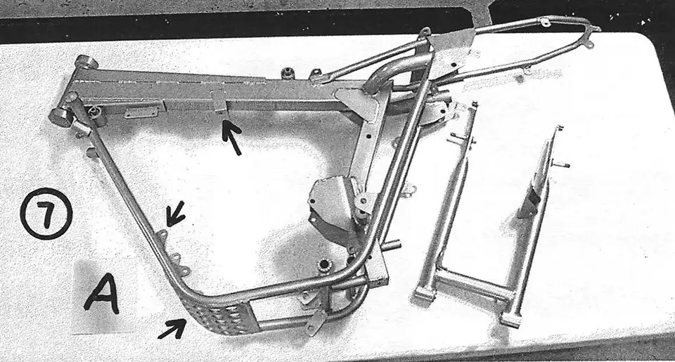
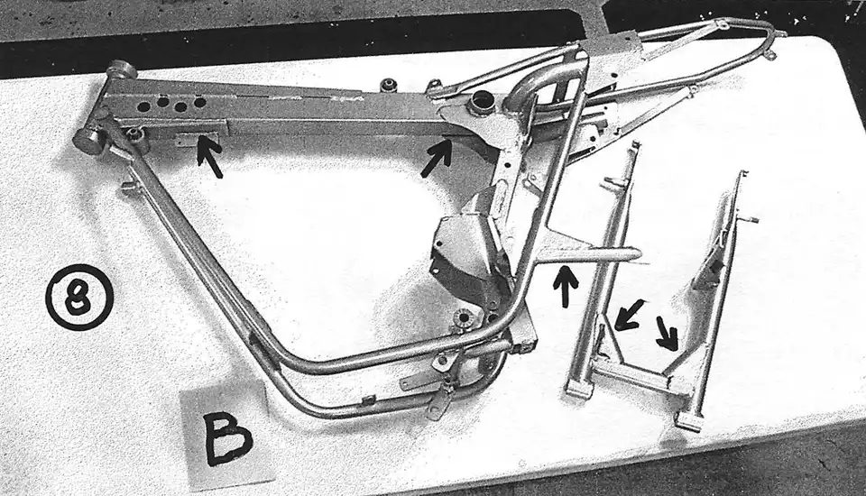
FRAME - I start with a late 1974 style frame and swingarm, which is the strongest AHRMA legal setup possible. First, strip the motorcycle down to the bare frame and check for cracks and bends. Then install the engine, pipe, and airbox, and closely inspect their fit. It is very important that all of the mounts for these items line up correctly and are not stressed! If a mount or bracket is not quite right, cut it off and set it up in the correct location.
Next, I take the frame/engine/pipe/airbox assembly to the welder. Any important frame work should be done with a TIG welder and the appropriate rod for the chrome-moly frame. First, fix the obvious cracks and bends and weld the aforementioned mounts or brackets back on. Then you can begin reinforcing the weak parts of the frame: the steering stem gussets, the breather backbone, the coil mount, and all of the other mounting tabs and brackets.
The steering stem gussets are lightly welded where they attach to the frame and can flex and bend. Tie them into the frame better with additional welds (see photo 1). The steering stem itself has held up very well for us, although by early 1975 the factory was reinforcing this area by adding a strap around the lower bearing race and welding it to the frame gussets. We use the stock ball bearing and race setup and keep them adjusted fairly tight.
The breather backbone is, in part, designed to hold the top of the steering stem in place. When landing from a jump, the forks transfer a tremendous amount of force to the steering stem. This force tries to pull the bottom of the steering stem forward and, when it can't, it tries to push the top of the steering stem back. Ultimately, this force is transferred down the length of the backbone and into the frame. Unfortunately, the rear of the backbone stamping is bent 90 degrees and extends horizontally to the left and right to attach to the frame. As a result, the backbone can actually collapse this horizontal section (the area where the rear loop for the tank strap is located) instead of transferring the force to the frame (yes, I threw that frame away!). We remedied this problem by adding triangular gussets that tie the backbone directly to the frame (see photo 1).
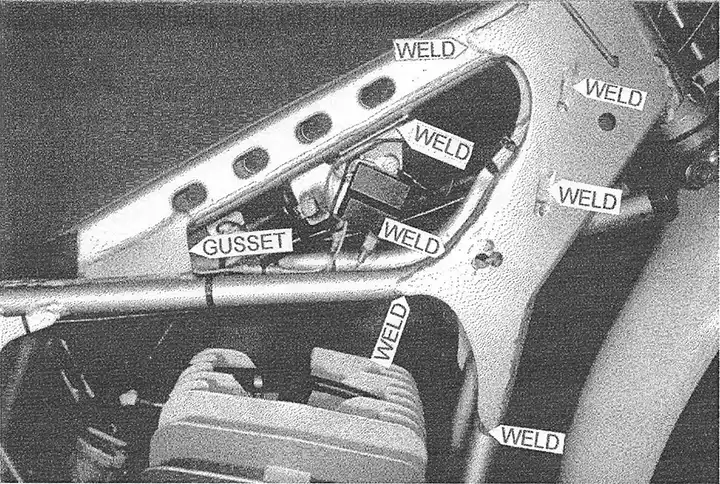
The coil mount can crack and eventually break where it makes a 90 degree bend to attach to the frame. As long as you have the frame at the welder's you might as well have him run a bead over this area (see photo 1).
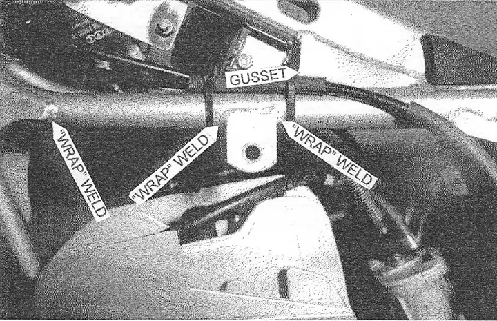
Many of the other miscellaneous mounts and brackets on the frame are prone to breakage because they are attached to the frame with a weld· on just one edge. This allows a "hinge" effect that can, . over time, fatigue the weld to the point of breakage. We "wrap" the welds around the sides of the bracket to eliminate the "hinge" effect (see photo 2).
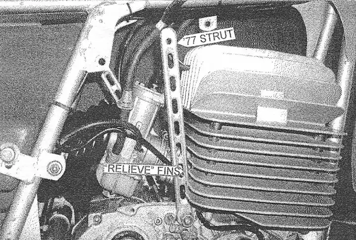
I also highly recommend using the struts that tie the engine to the frame, as they triangulate what is otherwise a square area surrounding the engine. Unfortunately, these struts make carb work very difficult. By using less bulky '77 right side struts and relieving the fins on the back of the cylinder, I was able to get the struts to rotate enough to allow adequate access to the carb (see photo 3).
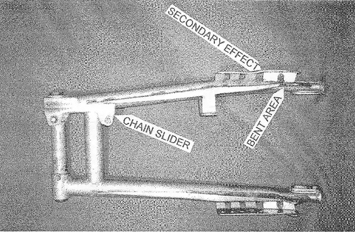
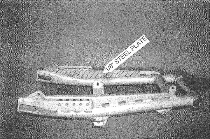
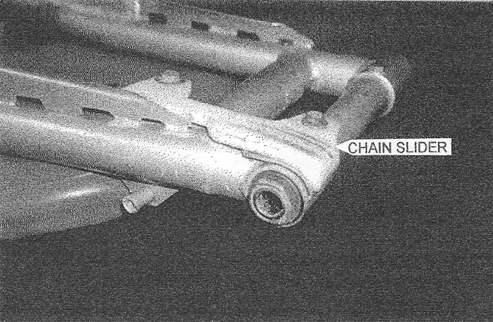
SWINGARM - The swingarm will bend fairly easily when the rear suspension is bottomed and, even with the proper shock setup, bottoming will occur. After bending several swingarms beyond repair (see photo 4), we decided to make some modifications to improve their durability. First, we cut out 1/8" steel plates and weld them into the back side of the factory gusset (see photo 5). Then, we make a chain slider out of 1/4" Teflon (see photo 6). Then, we use a jigsaw and a heat gun to fabricate the new Teflon slider. Attach the new slider using the oil filler bolt on the front and a small bracket to connect the rear to the back of the chain guide mount.
PAINT - First, I have the frame and swingarm sandblasted with fine "Black Beauty", a media derived from coal slag. Then the parts are primed with a urethane primer to fill minor imperfections and promote adhesion of the top coat. Finally, the parts are painted with "Martin Senour Tee/ One Stage Acrylic Urethane", which is extremely durable. I chose this system over powder coating because I can easily touch up areas that get worn or welded throughout the race season.
FORKS - The stock 35mm Ceriani's are excellent forks and require very little work to be race ready. We use stock internals with heavy springs from Barry Higgins of H & H KTM (770) 920-1371. The springs should have 10-20mm of preload. The fork caps will provide some of the preload and the rest can be achieved with washers for spacers. Use 15 or 20 weight fork oil (depending on your weight and riding style) filled to 6-1/4" from the top with the forks compressed and springs removed. Finally, disassemble your fork caps and make sure the check ball and spring are in good condition. I should also mention that we have used "Franks" replacement fork tubes in the past and, although the fit and finish was excellent, they bent under the extreme stresses of MX use. On the other hand, I wouldn't hesitate to use them for a show or play bike.
SHOCKS - We use "Ohlins Classic MX" shocks because they offer the highest quality, most advanced valving system on the market. Although the stock shocks for this frame were 13.5" long, I recommend using 14" - 14.5" shocks to bring in the rake and help the bike tum. Ohlins offers both 14.2" shocks or 15" shocks. We are currently using the 15" shocks with an internal spacer to make them 14.75", but I think the 14.2" shocks would be ideal for most riders. We mount them upright in the 4th hole back on the swing arm (see photo 7) and use "Eibach" 70, 80, and 90 lb. single rate springs (part numbers 1000.188.070; 1000.188.080; & 1000.188.090) to adjust for different rider weights and riding styles. Our experience is that single rate springs are better for vintage MX use because; with only 4" of wheel travel, using the first several inches for plushness doesn't leave enough travel to resist bottoming.
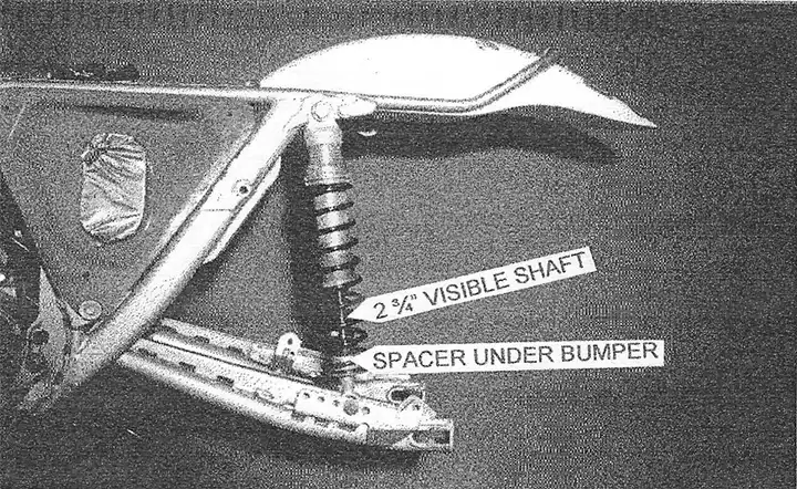
Regardless of shock length, AHRMA allows a maximum of 4" of actual rear wheel travel. AHRMA has a Shock Length Guide which outlines "maximum visible shaft length" for most brands of bikes, allowing the tech inspectors to estimate rear wheel travel without having to perform any calculations or remove the springs and take an actual measurement. Because Pentons had 2 different swingarms in 1974, as well as many different mounting positions, the listing for Penton just says "check"! We set up our shocks with 2-3/4" of visible shaft and always pass inspection. To help you meet these requirements, both Ohlins and AHRMA offer clip-on spacers that fit under your shock bumper and allow you to easily configure the visible shock shaft length at the track if necessary.
by Kent Knudson
Originally printed in the 2002 issue #15 of Still….Keeping Track
We asked Kent to write this article to help our members who are building or trying to maintain a Penton motorcycle for racing. The object is to find out what works and share the information.
Vintage racing is very competitive and if you want to win, you need all the help that you can get. Since Kent seems to have all the correct setups on his bikes, it makes sense to publish what he is doing.
The following outlines the various components, specs, and sources used to build our 250 engine that Kevin Brown won the AHRMA Sportsman 250 Expert and 40+ Expert National Championships with. Our engines are prepared by our friend, James Giddings of Giddings Machine Racing, who learned the art of building KTM engines while working in his father's Penton/KTM dealer-ship. I would also like to thank Barry Higgins for sharing his knowledge of these engines with us.
CASES - Check the cases closely for cracks and have them welded if necessary. Our current engine was cracked around the kickstarter stop bolt (on the bottom of the motor), the rear motor mount, and the ignition cover threads when we first bought it.
Don't worry too much about corrosion. Bead blast, thoroughly rinse and inspect corroded areas. I fill the pinholes that go all the way through with JB Weld or Devcon. Otherwise, warm the engine up and change the oil regularly and the corrosion shouldn't get any worse.
GEARS - If you are having trouble with missed shifts, inspect your gears closely. KTM's use undercut dogs for positive gear engagement and even the slightest rounding on the tips of these dogs will prevent full throttle upshifts.
In motocross, where the start is extremely important, a missed shift can be the difference between a holeshot and a back-of-the-pack start.
CLUTCH - Early 250 clutches used 8 steel discs, 7 copper clutch plates, and 1 spacer ring at the bottom. By mid- 1974, Penton was recommending the removal of the bottom steel disc and spacer. The use of a thicker pressure plate (part no. 54-32-006-100) was required to compensate for the loss in clutch stack height. We use the latter setup in conjunction with 1. 7mm wire diameter clutch springs (part no. 51-32- 001-140) that were used in the 400 engine. I would also recommend adjusting the spring pressure with a dial indicator to ensure even clutch disengagement.
For more information about KTM clutches refer to the Penton Service Data and Info binder which contains a section on General Service Info. General Service Info No. 10, dated July 25, 1974 is called "The KTM Clutch Story".
TRANSMISSION OIL - The aforementioned KTM Clutch Story, as well as the 1978 KTM manual, suggests the use of ATF in the transmission. We use one quart of Mobil 1 synthetic ATF.
CYLINDER - We use a stock, unported 1974 cylinder. Although many people swear by the Carl Cranke porting specs, we've found them to be unnecessary. The stock porting provides a very smooth, linear powerband that is still strong enough for Kevin to run with the big-bore bikes in the 40+ class.
DECK HEIGHT - Deck height is set at .030" - .035".
CONNECTING ROD - For our rebuilds, we use new connecting rods from EuroRods.
PISTON - We use original Mahle pistons with .003" clearance. Due to lack of availability of original 2-ring 250 pistons, we are currently using the later style 1-ring piston.
INTAKE - We are currently using an original GEM 250/400 Penton reed kit. Although this kit appears to be fairly small and restrictive, it helps contribute to the strong, smooth powerband that we were seeking. Just make sure you use the 250/400 kit, as I think they made a smaller 175 kit as well. The installation also requires drilling holes in the intake side of the piston skirt. The specs and procedure are outlined by GEM in their installation instructions. Replace-ment reeds can be purchased from Boyesen.
CARBURETOR - The stock 36mm Bing (2/36/102) works great. We use a #160 main jet, #283 needle jet, and a #35 pilot jet. We use a #1 (281) jet needle with the clip in the middle position. This setup has proven to be very versatile for us and has not required any changes in the last 3 years of competition. Although this should provide a good ballpark setting, any variance in engine specs, altitudes, or fuels may require different jetting.
FUEL - This seems to be a hot topic on the POG message board. My intent here is not to add any more fuel (sorry) to the fire, but we use the much maligned A VGAS. A VGAS lO0LL (100 octane low lead aviation gas) mixed 32: 1 with Yamalube R works extremely well for us; we used the same plug for a whole season. IT is very consistent regardless of where you buy it and it is reported to be comparable to (R+M)/2 103-104 octane (AV AGAS uses a different rating system). The knock (oops!) against AVGAS is that it is formulated for use in low-rpm, light load, steady throttle applications. The other options are, of course, pump gas, race gas, or a "blend" of the two. Pump gas can be very inconsistent and may contain up to 10% ethanol. Race gas is typically very high octane and should only be used in very high compression engines (although I've recently noticed several manufacturers offering race gas in the 100-105 octane range). In our case, we've used AVGAS since 1982 with excellent results.
AIR FILTER - Twin Air #154200
IGNITION - As long as you don't need a lighting coil, I would strongly recommend the PVL ignition, which is an internal rotor design. PVL also offers 4 different flywheel weights to help configure the power delivery of your engine. On the 250 engine we opted to not use any additional flywheel weight and the engine is still very smooth and tractable.
TIMING - Ignition timing is set between 2.5mm and 2.6mm BTDC.
SPARK PLUG - NGK B8HVX gapped at .024". The VX is NGK's top-of-theline plug for this application and features a fine wire platinum center electrode and a tapered ground electrode for maximum efficiency.
EXHAUST PIPE - Stock 1974-75 enduro exhaust.
KICKSTARTER LEVER - Newer style lever supplied by Alan Buehner
SHIFTER - Original Hi-Point folding shift lever.
SPROCKETS - We use a 14 tooth 520 PBI Pro steel front sprocket (#93-14) and a 57 tooth 520 PBI aluminum rear sprocket (#5257-57).
BEARINGS and SEALS - We start each season with all new bearings and seals, which sounds like overkill but it's a lot cheaper than the cost of attending another race (transportation, hotel, entry fees) due to breakage. All clearances are set using the factory manual.
GASKETS - Complete gasket sets are supplied by Alan Buehner.
PAINT - For the silver engines we use PJl silver barrel paint #17BRLS. The blue K1M oval is hand painted with Martin-Senour Acrylic Enamel - GM fleet blue 99L 11540.
by Kip Kern
Originally printed in the 2002 issue #14 of Still….Keeping Track
I was asked to provide an article pertaining to "what a person should look for when buying a Penton" whether for restoration, racing, or both. What I have done is try to provide an article covering the "Steel Tank" years, 1968-1971, and show differences and rarities pertaining to each year of manufacture. Most of the information covers restoration and allows the reader/ restorer to decide if they want to race the machine after their work is complete.
What I did not cover was the basic available knowledge items such as: seat size (68-69, some 70, short saddle vs 70-71 longer saddle), Rims (68 Borrani shouldered aluminum vs 69-71 Radaelli chrome steel), 68 chrome spokes vs 69-71 painted steel, controls ( all years are identical), the short chain guard on the 69-71 bikes, and lastly, enduro/ lighting packages. Each of the above items can be viewed in the Penton parts manuals, 001 and 002.
As I stated earlier, I did not cover every detail pertaining to the 68-71 Penton Sport Cycle, the majority that can be found in Penton parts manuals 001 & 002. I hope that I have provided some ideas of differences of each year Penton to aid the owner, restorer, and racer. Hopefully this will help you when deciding on a certain year Penton Steel Tank project! This info is by no means written in stone. It is simply "neat" stuff I have come upon during my stint as a restorer.
By Doug Wilford
Originally printed in the 2001 issue #13 of Still….Keeping Track
Are you having problems shifting your Sachs engine? This article is being written to help or correct those problems.
Most problems in shifting the Sachs engines are not confined to just one item. It is usually a combination of items that makes for missed shifts. I will try to cover all the items that can cause bad shifting besides adjustment. Proper adjustment will be the last and most important part of this article. If you can, put a plus or okay next to the items mentioned, as trouble causing. Let us start with the outside as I have seen this happen:
Trouble Causing:
- Shift lever mounted too high (rubs on case lettering)
- Transmission oil too heavy a viscosity. (Use a 10-30 motorcycle transmission oil, 700cc)
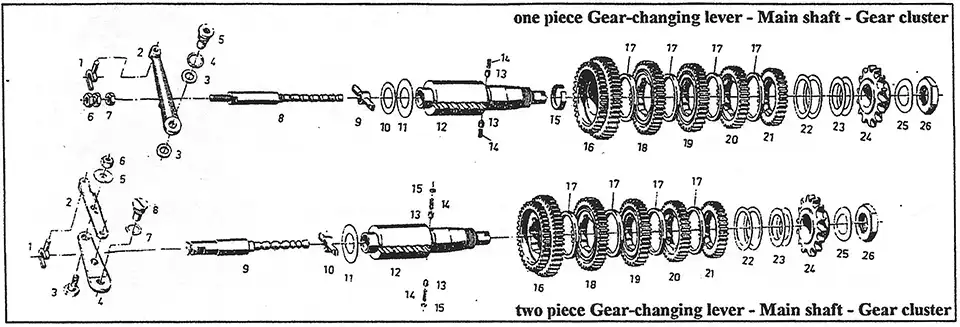
Internal pieces to check (refer to parts illustration #1) - Selector rod #9 grooved by #13, 14, 15 plunger cup.
- Plunger cups frozen, missing, or badly worn.
- Selector Key #9-10 worn (very important).
- Sliding gears #18, 19 - 2nd & 3rd key contact areas not rounded. All the above in the main shaft assembly should move without binding and be free, with the plunger detents working the shaft into the detents smoothly.
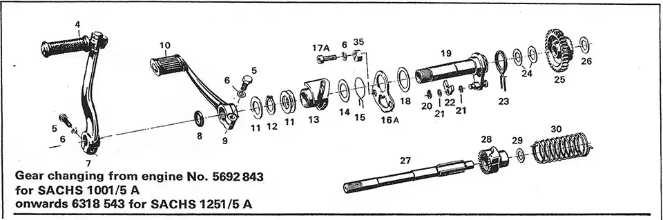
Shifter assembly (refer to parts illustration #2) - Check that the pawl spring # 15 is making contact on both sides of the selector pawl #22. This is important as this moves the selector pawl #22 into place against the teeth of the selector boss # 13.
- This whole assy., shifter assy. #12-23 is shimmed together. It must move free within itself, but no slop.
NOTE: To adjust shifting, the clutch gear assy. must be
removed!!!
INSTALLING THE SHIFTER ASSEMBLY
The shifter assy. must be shimmed, use shims #24. These fit over the kick starter shaft at the base against the cases. Slide the assy., down over the kick start shaft #27, the adjusting plate # 16 should make contact with the mounts just before the shifter assy. bottoms out. The adjusting plate #16A needs to be in a non-binding position. After shims are .determined, slide the shaft assy. back up the kick start . shaft and install the shifting fork, selector arm and pivot screw, all wile sliding the assy. back down. Install mounting bolts with cams and tighten with the cams moved out of the way. Using shims #11, shim the shifter assy. so you can put a straight edge across the cases and the selector assy. making contact at all three places. NOTE: if the selector arm has an overly amount of play at the pivot point you may need to find a shim washer to eliminate some of the slop. This is rare, but it does happen. If you have now said: "Okay, I'm ready", we will move on to the adjusting procedures.
A special tool here is a must. It is called the "Transmission Adjusting Tool" and is not a Sachs item. Ted Penton made this tool for the Penton service dept. and the Penton parts list and the "Hi-Point Accessories" catalog. It or a reproduction of this tool is available thru Buehners Supply (phone #216-651-6559). The reason for this tool is to simulate what the left side cover does when the engine is together. It is impossible to make accurate adjustments without this tool. You may get lucky once in awhile, but to be sure, use the tool.
Step one: Make sure you can shift from 1st thru 5th or 6th (which ever you are working on). The bolt in the middle of the selector arm is a concentric ( on the later engines). I will make a separate procedure for the early 5 A engines. Bend back the locking tab on the top and loosen the 10mm nut if you need to move the concentric 13mm bolt. The object is to have equal movement up and down against the selector rod #9. If you can get full engagement of 1st and 5th or 6th, it means you are now inside the ball park.
Step two: Now we want to work between 3rd and 4th gear. NOTE: I usually put the shift lever in about a 7 o'clock position for ease of holding it in position (engine or bike laying right side down) while I turn the counter shaft sprocket or the clutch inner hub. Please do not try to make these adjustments with the clutch assembly still in place. If you can get 3rd and 4th lined up, it makes things go a lot easier, but this is not an absolute. Move the shift lever to engage 4th and hold the lever tight up. Reach in with your fingers and see if you can feel more up pressure or down pressure of the fork # I against the selector rod #8 or 9. It is perfect if the fork is loose while you are still holding up pressure on the shift lever.
Move the shift lever down to engage 3rd gear, again holding pressure, now down, on the . shift lever. Reach in and feel where the pressure is between the two. If the fork is loose in the slot with down pressure on the shift lever again, this is perfect. Most of the time (95%) you will have to determine which way to turn the concentric (13mm) to add either more up or down movement on the selector rod. You are moving the selector rod, but checking the movement using the shifter fork. Once you can feel that you have equal pressure in both directions, tighten the 10mm nut and try again. And again, then shift from 1st thru 5 or 6 and back. At this time I check my fork pressure in the high gear and the low gear, again they should be the same, IF the 3rd and 4th adjustments were the same.
Now loosen and set the left cam, upshift to any gear (3rd or 4th) holding the shift lever tight up, move the cam over to make contact with the pawl, and tighten the alien head. Make sure the pawl does not make contact with the cam before the selector is all the way. Repeat the procedure for the right cam, but you will need three hands and a small crew driver to hold the shift lever tight down. Move and hold the cam in place while you tighten the mounting alien head. Okay, now shift thru all gears until you are happy. Make sure you have tightened everything, and put the lock tab back on the 10mm nut on the selector arm. Remove the tool, reassemble the engine and go have fun.
Here are 10 very important items to check:
(Taken from a previous article by Kip Kern.)
refer to illustration #1
- The main shaft #12 is shimmed properly between the case halves.
- The shift key #9 is in excellent condition.
- The selector rod #8-9 is not grooved or worn.
- The selector rod detents #13-14 are in excellent condition.
- The transmission gears are spaced properly and not worn on the insides.
- The two springs #15-23 on the shifter assy. are OK, making contact equally against the pawls.
- The shifter assy. is shimmed properly, from the inner case.
- The space between the shifter assy. and the clutch cover (special tool) are shimmed properly, prior to installation of the clutch assy.
- Properly shim the shift arm pivot point in the case.
- Use an unworn shift fork #1.