

KTM bikes from 1978-88
What's the Difference?
by Alan Buehner
Originally printed in the 2006 issue #32 of Still….Keeping Track
Since the post-vintage racing scene is seeing more and more participation each year, I felt that it was time to focus some attention to the 1978+ KTM machines. This article will help identify the years that new models were being introduced and the major changes that were happening. Although KTM was slow in incorporating reed valves, water cooling and single rear shock suspension to their bikes, they did their homework before doing so and avoided many of the problems that the Japanese bikes encountered.
KTM bikes, up to model year 1983 are Post-Vintage legal as long as they have twin shock rear suspensions and are not water cooled.
1978 – Last year of the MC & GS frames
This was a repeat of the 1977 model bikes in the MC-5 or GS-6 frames with minor changes made to the frames, air boxes, and swing arms. They were available in engine sizes 125/ 175/ 250/ and 400. They were equipped with 35 or 38mm Marzocchi front forks.
1979 – First year of the 420
The MC-5 and GS-6 frames were discontinued and a new generation frame, the MC80/ GS80 was introduced. This was an all-in-one frame that was basically set up for m-x (like the 70's CMF bikes) and could be converted to a GS by bolting on a rear frame loop and adding lighting. The 125cc/ 175cc/ 250cc/ and 400cc engines were still available. The new 420cc MC80 was introduced to the line-up. It was to be the replacement for the 400cc engine and provided plenty of controlled power without the power band “hit” that the 400 gave.
1980 – First year of the 495
This was the last year for the 400cc engine and the first year for the powerful 495cc. In July the following engines were introduced: the 420cc (type 560)/ 350cc (type 561)/ 390cc (type 562)/ 495cc (type 563). All bikes were available in the MC or GS versions. This was the last year for the 175 engine.
1981 – First reed valve & water cooled engines
The 250/II (type 541) was introduced in October of 1980. It was available as a 5 speed MC or 6 speed GS. In January the following bikes were available: 125cc/ 250cc/ 350cc/ 390cc/ 420cc/ & 495cc. In March the 125cc engine was changed and available in 2 versions: 125II/RV (air cooled with a reed valve) and 125II/LC (liquid cooled with a reed valve). This was KTM's first production of a water cooled and reed valve engine.
1982 – First Pro Lever rear shock
This was the first year for the KTM “Pro Lever” single shock rear suspension. It was introduced in December 1981 on the 250cc & 495cc MC bikes and they also came equipped with 40mm Marzocchi front forks. The 250cc/ 390cc/ & 495cc engines were equipped with reed valves. The 250 came in 2 versions: 250GS (type 541) and 250MC (type 542). In June the first 4 stroke KTM bikes were introduced in GS form only. They were available in 2 sizes, 350 & 500cc with Rotax engines built by Bombadier, had “Pro Lever” rear suspensions, and were the first KTM's to come with front disc brakes.
1983 – First water cooled 250
In November of 1982 a new model, the XC was introduced. This was a desert enduro that was made to compete with the Husqvarnas being ridden in California. The models available were: 125cc MX-XC-GS / 250cc XC-GS/ 420cc GS-XC/ and 495cc MX-XC. In June the 250cc MX/LC (type 543) was released and became the second engine in the KTM stable to become water cooled. All bikes were equipped with 38 or 40mm Marzocchi forks, the 495 came with 42mm Marzocchi forks.
1984 – First KTM 4-stroke engine
In September of 1983 changes were made to the 250cc (type 543) engine and it was available in MX, MXC or GS form. In November of 1983 a new 125cc (type 501) engine was introduced and was available in MX or MXC form. Also in November the Rotax engine was available in 348cc GS/ 506cc GS/ & 560cc GS form for 1984. These were the last models for the KTM/ Rotax bikes. In March KTM released their own 500cc & 600cc 4 stroke engines in GS or MX form. This was the last year for both, the 420cc which was available in GS or MXC form, and the 495cc which was available in MX or MXC form. They and the 4 strokes came with “White Power” upside down 40mm forks.
1985 – Front disc brakes
An all new 500cc (type 565) 2-stroke was introduced to replace the 420 & 495. It was available in MX, MXC, & XC-GS form. The line-up of bikes also included 125– 240– 250– 300cc. These were available in MX, MXC, GSXC, & GS forms. All bikes were equipped with front disc brakes.
1986 – Rear disc brakes
KTM went small and introduced it's “Pro-Mini” 80cc (type 490) MX bike. A new 350cc (type 555) engine was also introduced and was available in MXC & GS form. All bikes were equipped with rear disc brakes. This was the last year for the (type 544) 240-250-300-350cc engines. “White Power” forks were available for all 125cc & larger bikes.
1987 -
A new (type 502) 125cc and (type 545) 240-250cc engines were introduced and were available in MX or Enduro form. The 350 was also available in MX or Enduro form and the 500 was available in MX form only.
1988 –
The new LC4 (type 580) 4 stroke engine was introduced and was available in 500 & 600cc sizes. The lineup included the following 2-stroke engines: 125cc (type 502), 240-250cc (type 545), 350cc (type 555), & 500cc (type 565) and they were available in MX or Enduro form.
What's The Difference?
by Alan Buehner
Originally printed in the 2006 issue #31 of Still….Keeping Track
The purpose of this article is to show what the differences are between the Bing carburetors used on the Penton motorcycles from 1968 thru 1975 and the internal parts used in them. To simplify things for this article, I will be comparing the Bing 27, 32, and 36mm carburetors. Many of the parts used on the Bings are consistent and are interchangeable. These parts include: float bowl gaskets, floats, carb bowl clamp screws, idle adjustment screws, throttle stop screw, top cover screws, cable adjustment screws, pilot jets, main jets, and jet holders.
Consult the specifications in the Penton Owners Manuals for suggested sizes for needles and jets in setting up a Bing carb. Check the Penton Parts Lists for the Penton part numbers and Bing interchange part number for any Bing parts.
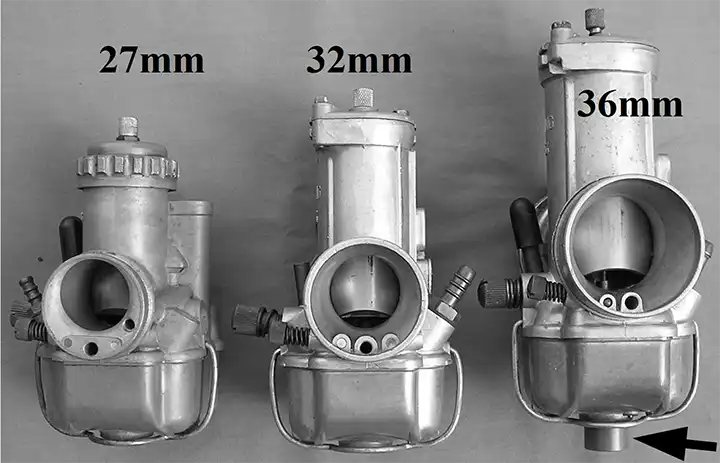
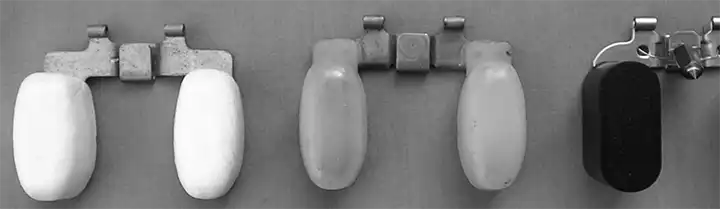
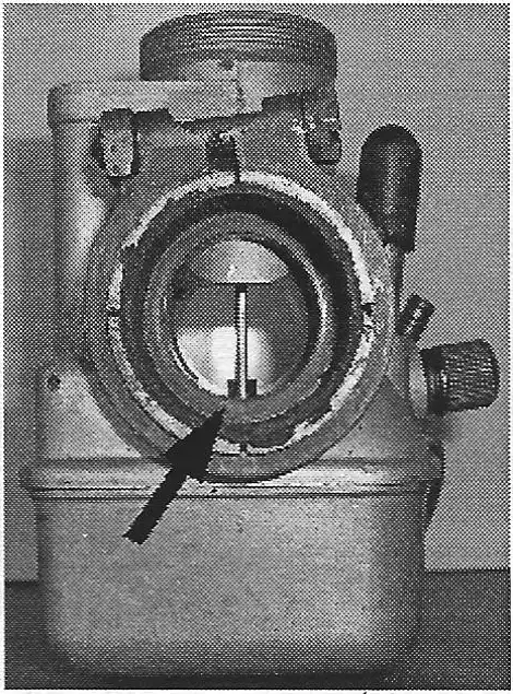
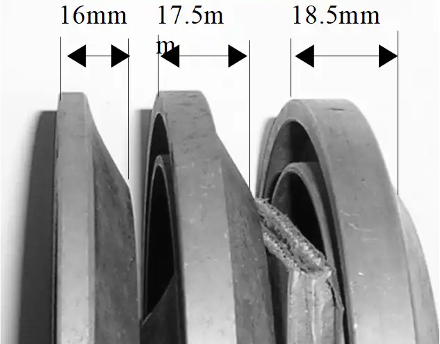
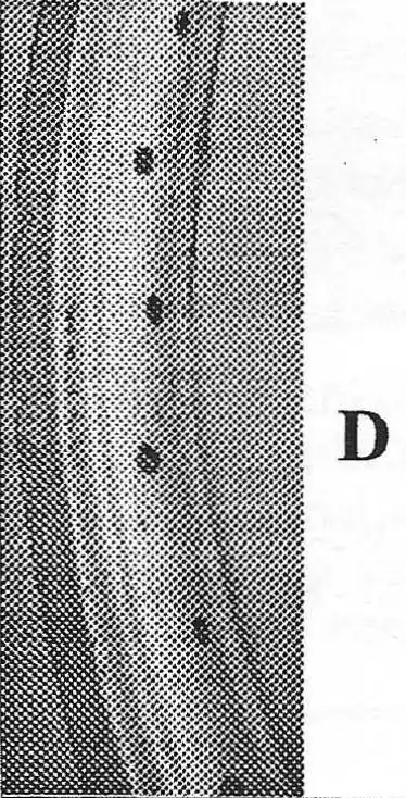
Bing carburetor bodies
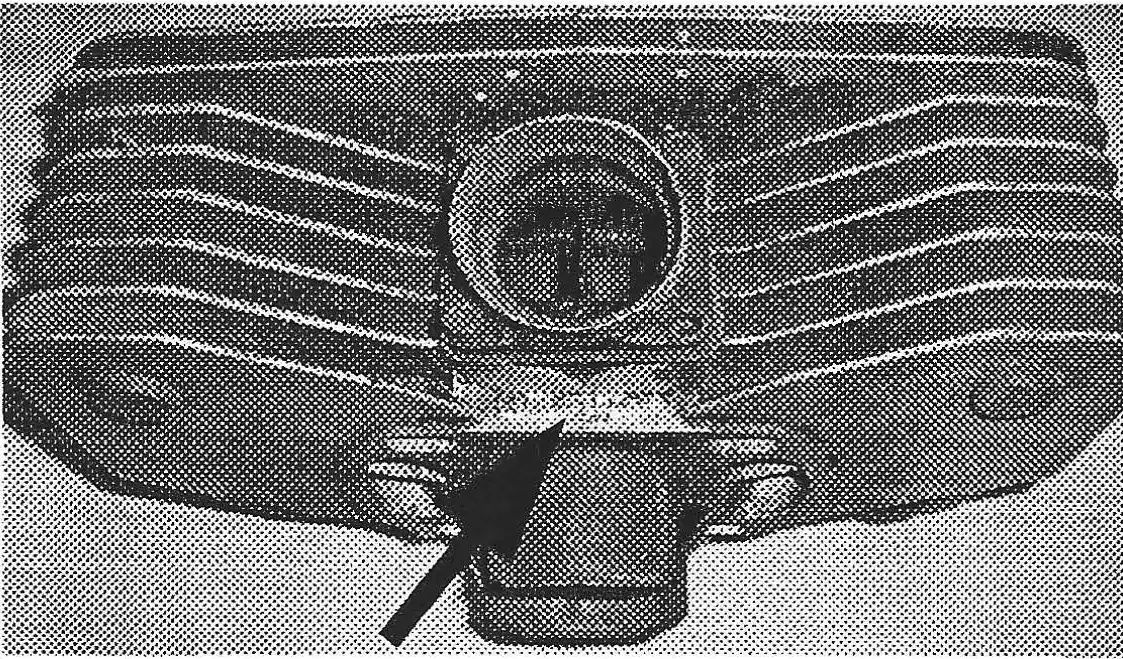
As can be seen from the above photo, Bings can be easily identified by size when compared to one another however, the bodies are deceiving in that each body size was used for more than one size by enlarging the intake bore. The 27mm above could also be a 24mm or 26mm. The 32mm above could also be a 28mm or 30mm. The 36mm above could also be a 38mm. The best way to verify the size is to check the model numbers stamped on each carb. Example: 1/36/103 = 36mm (the number between the 2 slash marks). NOTE: the 38mm carb models and some of the 36mm use a float bowl with an extension on the bottom for the main jet (see arrow).
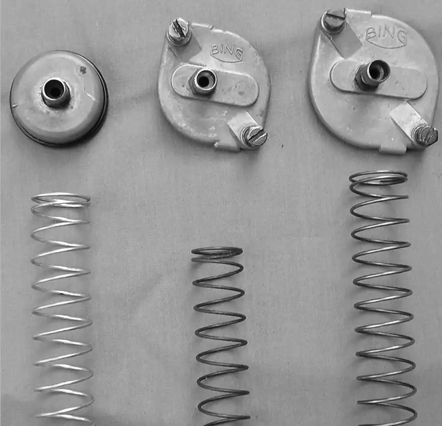
Bing covers & springs
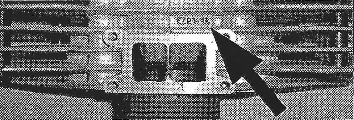
The covers on the Bing carbs are distinctly different in size. The 32mm and 36mm sizes shown are set up with only one adjustment screw for the throttle. Most of these are set up with another adjustment screw for the choke cable.
The springs for the throttle valves are different in lengths and also diameter of the windings in order to fit inside the throttle valves.
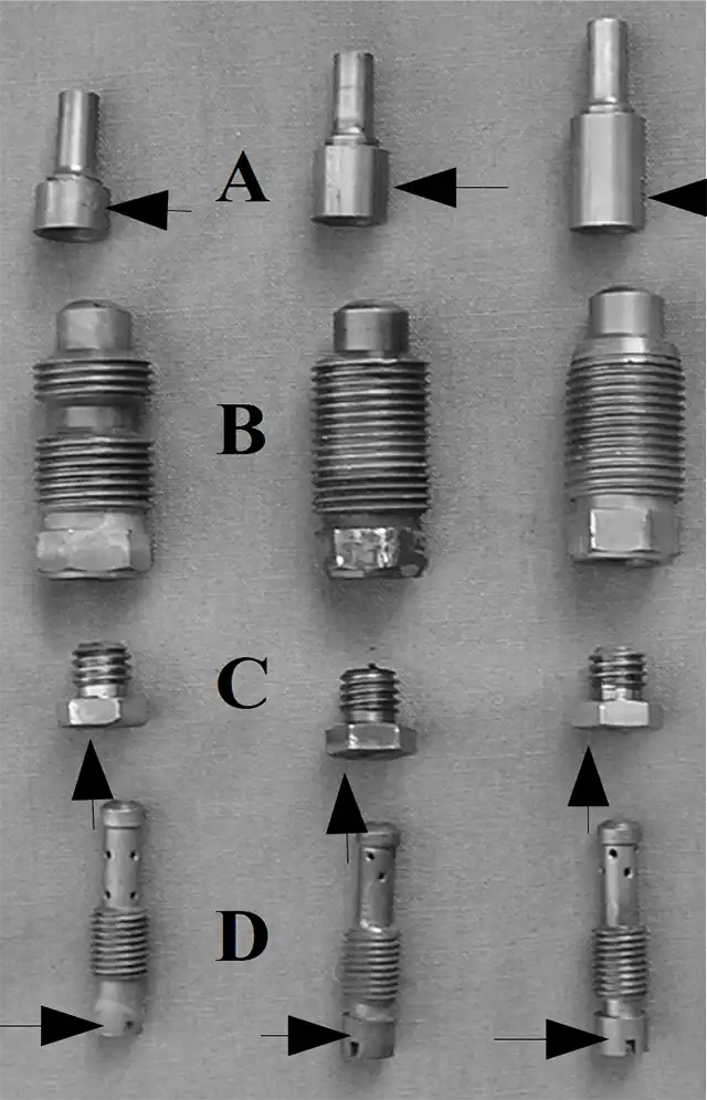
Bing internal jets
Items “A” are needle jets. They are not interchangable, and as can be seen, are different in the length of their lower bodies. Sizes are stamped on the side.
Items “B” are the jet holders. They came in 2 different styles and are interchangeable.
Items “C” are the main jets. They are interchangeable and come in wide selection of openings from size 80 thru 200 as engraved on them.
Items “D” are the Pilot jets also known as idle jets. These are interchangeable. Sizes are engraved on the side of the screw heads.
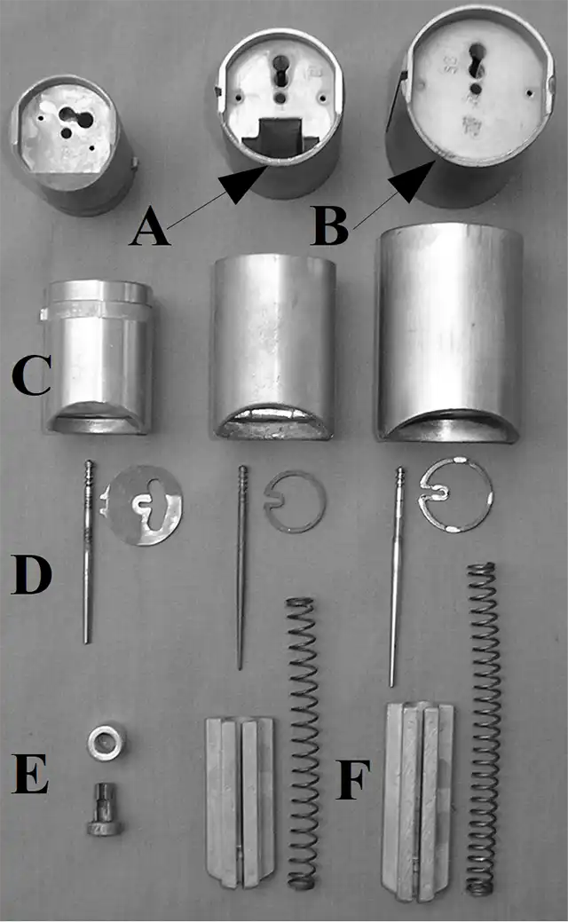
Bing slides & needles
The Bing throttle slides (C) are differ-ent in length and diameter as shown. They are available (A) with or (B) without cut-outs to accept choke air valves (slides F).
Needles (D) are different in length. Sizes are identified by the number of rings (1, 2, or 3) on the needle just below the adjustment slots.
The Bing 24, 26, &27mm carbs have a side choke assembly that use a starter slide and sleeve (E).
The Bing 32 & 36mm carbs use a choke slide (F) that fits in the slot of the throttle slide. The choke slides and springs are of different lengths. These chokes are not necessary for starting a bike and it is common to find them missing.
Bing floats
Bing floats are interchangeable They came in three different styles: white styrofoam, yellow plastic with a sealed air chamber, and black styrofoam.
A Doug Wilford tip for Bing Carbs
To remove the old float needle seats, tap the opening. Leave the tap in place, heat up the carb body, and use the tap as a tool to pull the old seat out. While the carb body is still warm, insert the new float needle seat.
On Bing 24, 26, & 27mm carbs with side chokes, make sure that the starter slide (item E) is installed in the carb and that it still has the wax sealing material inside it. If the starter slide and it's wax is missing, the engine will start but it will run rich as the engine warms up.
by Alan Buehner
Originally printed in the 2006 issue #30 of Still….Keeping Track
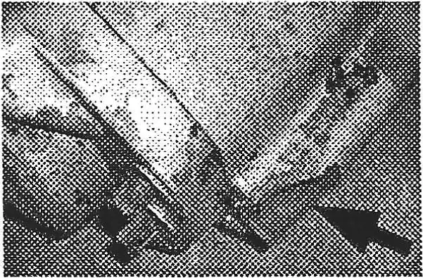
Magnesium backing plates
Remove, clean, & grease the pivot pin (a) on a regular basis. Lack of lubrication will cause the magnesium to wear by the pivot pin and wear out the mounting hole (b), resulting in a loose pivot pin and loss of braking pressure.
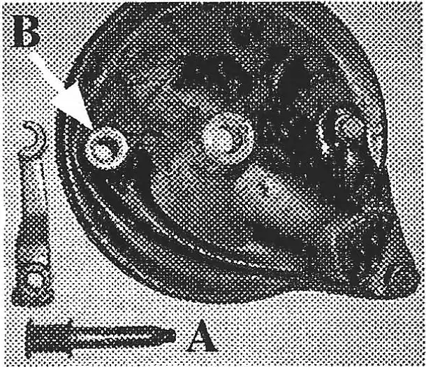
A simple fix to keep the pivot pin greased without having to disassemble the rear wheel is to install a zirk grease fitting in the backing plate at "C". Caution: when using a grease gun, do not pump a lot of grease into the fitting. The excess grease could build up on the inside on the brake shoes and lining.
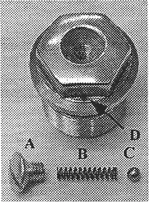
Vents on fork tube nuts.
When changing your fork oil, and or after a wet or dusty ride, check the vents on the fork tube nuts. Remove the screw (A) in the center, remove the nut from the fork tube, and check that the spring (B) and ball (C) are clean and dry. Replact;.them if they are rusty or pitted. Use a fine wire to make sure that the vent hole (D) is not obstructed.
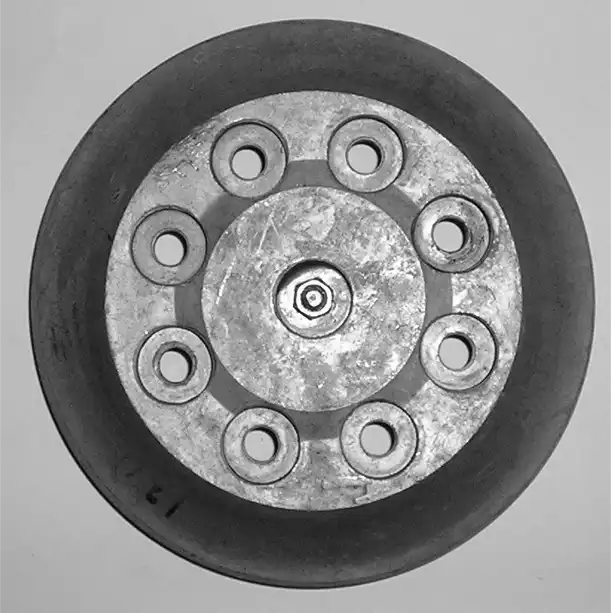
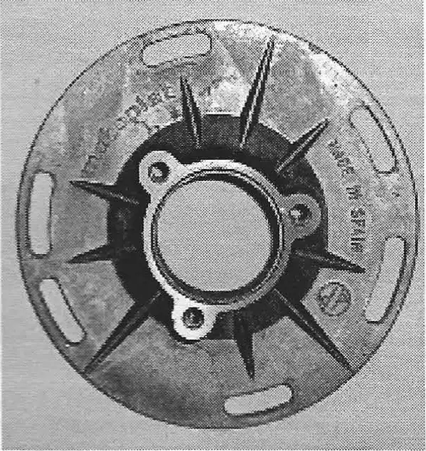
Cush drive bearings & rubbers on CMF's
The cush drive rubbers should be checked for wear on a regular basis on bikes that are being raced, especially on the 1972-73 Jackpiners. The torque on the l75's is powerful enough to rip the lugs off of the hubs if there is too much side-to-side play between the sprocket carrier and the hub from worn rubbers. The easiest way to check for excessive wear is to grab the rear sprocket, with the rear tire resting on the ground, and try to move the sprocket back and forth. With good rubbers, there should be little or no movement of the rear sprocket. With worn rubbers, there will be very noticeable movement of the rear sprocket.
If you are racing these bikes, check the bearings on the sprocket carrier on a regular basis. These bearings will wear out faster than the hub bearings especially under wet and dusty conditions.
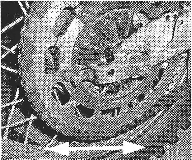
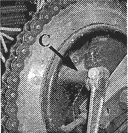
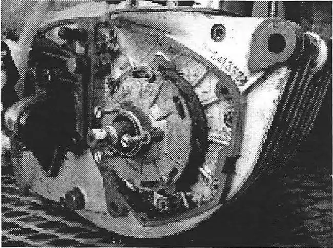
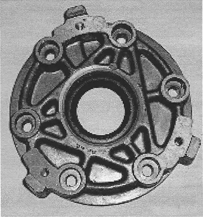
KTM engine mounts - especially 400 /420 /495
All mounting bolts on the KTM engines should be checked on a regular basis to make sure that they are tight. All mounting bolts on the 400 / 425/ 495 engines should be checked after each day of riding. Engine vibration will cause the nuts to loosen. If they get loose, the engines start to wiggle around in the frame and then the magnesium cases start wearing away. Left unchecked the engine will wind up looking like this. The steel frame mounting tabs will wear into the case, the bolts will wobble out the holes and the cases will eventually break. If you are still using the original 30 year old nylock nuts, replace them with new ones.
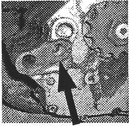
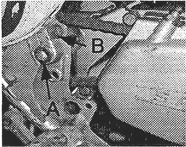
Swing arm mounting bolts.
A commonly overlooked maintenance item is the swing arm bolt (A). It should be removed, cleaned, greased, and re-installed on a regular basis on all bikes that are being ridden. The reason for this is to prevent the bolt from freezing up inside the swing arm and becoming impossible to remove without cutting it out. On bikes with the conical rear hubs, the two screws on the swing arm should be removed and make sure there is plenty of oil around the inner axle (see maintenance instructions in your Penton/ KTM Owners Manual).
If the swing arm bolt is frozen inside and will not come out, check the swing arm to see if there is any play at the swing arm. If not, you can leave it as is and use the bike for easy riding. In many circumstances, the bolt will turn, unthreading itself on the left side of the frame as it pushes the frame away from the swing arm. Do not beat on the frame to try and loosen the bolt. The only way to get it out is to remove the engine, spread the frame at the swing arm enough to cut the bolt, the left side first, then the right side.
Note: New old stock and used swing arm bolts are difficult to find.
After re-installing the swing arm bolt make sure that the Allen head pinch bolt (B) is tight. This bolt should be checked on a regular basis to prevent it from loosening.
A Doug Wilford tip for Sachs Motors
When pulling the counter shaft sprocket, loosen the nut but do not remove it. Back it away from the sprocket by about 1/8", install the puller, and then remove the sprocket. The nut will prevent the sprocket from flying across the garage when it "lets go".
Also remember to use a "protective cap" on the end of the mainshaft when installing the puller to prevent the split ends of the mainshaft from flaring out and breaking.
What's The Difference
by Alan Buehner
Originally printed in the 2005 issue #29 of Still….Keeping Track
At first glance it is hard to distinguish a 250cc cylinder from a 400cc cylinder if they are bolted onto the bottom end. They both have large fins and the bolt hole patterns on the heads are the same. A quick check of the serial number on the engine case (ignition side, just below the cylinder) will tell you what size it is. The first number is the year, the next two numbers are the code for the size (54=250 / 55=400).
KTM was consistent in their manufacture of 250 and 400 cylinders from 1973 to 1982. They were all piston-port, air cooled cylinders with large fins. Although KTM did not introduce reed valves until 1982, they performed well and were competitive up until their reed replacements. (note: the 400 was discontinued and replaced by the 420) Looks can be deceiving. Even though the cylinders looked the same during their time span, changes were made.
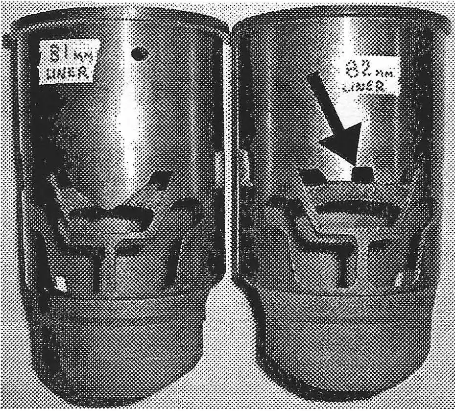
The most obvious and widely unknown change KTM made was the sleeve/bore size. The 250's started out with 71mm and were changed to 71.25 in 1977. The 400's started out with 81mm and were changed to 82mm in 1978. What this means is that when it comes time to re-sleeve the cylinder, you must identify what size sleeve you need.
All KTM cylinders are identified by casting marks which are found above the intake ports (on the early 250's the markings are below the exhaust port). They are easier to see and read if the intake manifold is removed.

Examples of what you can expect to find are:
| 200 | 400 |
| EZ 71/1R ELKO | EZ 81/1R |
| EZ 71/2R | ELKO EZ 82/2R |
| EZ 71.25/2R |
EZ is the manufacturer's identification which stands for "Elko Zylinder." The number before the slash mark indicates the sleeve size and standard piston size. The number after the slash mark followed by an R identifies which revision the cylinder is.
The revision numbers identify the subtle changes that KTM made to their cylinders. These changes were made to the intake, exhaust, and transfer ports where they were raised slightly (approximately 1mm) to change the performance (power band) of the engine. The following , measurements show what the differences are:
| Cylinder | Top of exhaust port | Top of transfer ports | Top of rear boost port |
| 71/1R | 35mm | 49.5mm | 52mm |
| 71/2R | 34 | 50 | 47.5 |
| 71/4R | 34 | 49.5 | 49 |
| Carl Cranke | 33 | 48.5 & 47.5 | 48.5 |
| 81/1R | 38.25 | 55.5 | 55.5 |
| 82/2R | 39 | 54 | 56 |
Note: distance from top of cylinder to bottom of ports were unchanged. I included Carl Cranke's 250 porting specs to show how KTM's changes compared. Carl's specs also call for widening of the exhaust and two of the transfer ports. The width of KTM's ports appear to be unchanged.
by Alan Buehner
Originally printed in the 2005 issue #28 of Still….Keeping Track
The following article was written from information provided in "Let's Do It Right by John Cobb" of the March 1973 Keeping Track.
The Bing carburetors have a lot of parts inside them and they can be intimidating if you are having problems with it. The secret to getting the carburetor to perform properly is to isolate where the problem is occurring in relationship to the throttle, what the jetting is, and if the parts are installed correctly.
The information in this article is relevant to all Bing carburetors used on the Penton motorcycles. The following are examples of the different size Bings that were used:
- 100cc & 125cc - 27mm Bing
- 175cc - 30mm Bing
- 250cc - 36mm Bing
- 400cc - 38mm Bing
Before we start talking about "How to Jet Carburetors", lets see if this is where the fault lies.
- Make sure the bike has good compression. If not, it will load up quite easily. If compression is low, check the rings for wear and clearance.
- Make sure the timing is set right. 100cc & 125cc should be 2.6 to 3.2 before top dead center. 175cc should be 3mm before top dead center. 250cc & 400cc should be 2.55mm before top dead center*
NOTE: check the spec. sheets of the repair manual for KTM motors for the before top dead center ignition timing for 1976+ GS & MC motors. - Your ignition coil may be faulty and when the bike is warm, it could cause loading up, making you think it's carburetion, when in fact its a bad coil. If its a Motoplat, have the coil and stator checked out. If it's a points system, check out your condenser.
Think of your carburetion as a chart; this will make it easier. Now if your bike is loading up from 0 to ¼ throttle, your problem probably lies in the idle, pilot jet.
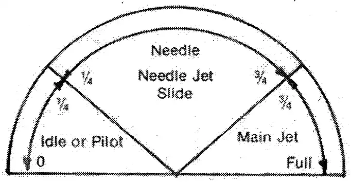
If the bike loads up in the mid-range or ¼ to ¾ throttle, your problem probably lies in the following: needle, needle jet, slide.
If it loads up from ¾ to full throttle, the problem probably lies in the main jet. Now we have figured out where it's too rich.
But if it's too lean, you may get the same effect. Be careful about jetting.
CAUTION: With a lean condition, the engine is running out of fuel. Usually it will just quit. But if you go down the road and it's lean in the main jet range, problems will occur, such as piston and ring seizure, or rod failure, to name a couple. Check the color of your spark plug electrode porcelain. If it is white or light tan the carb is lean. If it is black the carb is rich. If it is light brown or dark brown your carb is "right on the money."
Here are a few settings and what we have available for 100cc and 125cc, 24- 26-27mm Bing Carburetors. These jets are listed from leanest to richest.
- Idle jets: #30, #35, #40, #45
- Needle jets: #2.70, #2.73, #2.76
- Needles: #5, #4
- Main jets: 85 to 155 in graduations of 5.
We have found the best jetting on the 100 & 125 bikes is:
- #4 Needle
- #2.70 Needle Jet
- #45 Idle Jet
- #140 Main Jet
On some earlier bikes or a bike you have problems with, this is the jetting we use.
- #5 Needles
- #2.73 Needle Jetting
- #35 Idle Jetting
- #140 Main Jetting
If you are using this jetting or use it as a base, you shouldn't have any problem. Also when doing any jetting or carburetor work, you should remove the carburetor and completely clean it inside and out. Then set the float level. The float level for the Bing carburetors are as follows:
Turn the carburetor upside down. Hold the floats up and let them down slowly. As the brass tab on the float touches the ball bearing on the end of the float needle, the floats should be parallel. Here are a few settings and what we have available for the 175cc and 250cc engines:
- 30mm Bing 36mm Bing
- 3rd notch needle position 2nd notch
- #2.73 needlejet #2.83
- 30 idle jet #30
- 150 mainjet #165
When reassembling the carb, make sure that the vaporizer is positioned correctly. It has a half-moon cut out and the open part must be facing towards the piston. If it is aimed towards the air box, the bike will start and idle but as soon a you put the bike in gear and put the engine under load, it will die.
CAUTION: Unless you have owned the bike since new, be suspicious of main jets and needle jets. Back yard mechanics have been known to drill out the jets to make them larger. They have also been known to reassemble things wrong (without the help of a manual) by mis-adjusting the floats. On the 27mm Bings with the side chokes, make sure that the parts to the choke are installed. Check the bottom of the starter slide to see if the wax like sealer is still there. If the wax like material is missing, the choke will always be activated resulting in the engine continuously running rich.
by Alan Buehner
Originally printed in the 2005 issue #27 of Still….Keeping Track
There are 2 styles of “bearing plates” (we refer to them as clutch actuators) that were used on KTM motors, the old style (figure A) and the new style (figure B).
The old style was used on the first 1972 KTM 175 motors and used on all other sizes of KTM motors up until the 1980's. The New style was introduced in 1976 and was equipped on some but not all motors up until 1979.
The old style bearing plates had problems. The biggest one was the housing which was made of magnesium. It would wear from the rotating action of the cam every time the clutch was used. The wearing will cause the cam to wobble around loosely in the opening of the housing and cause oil to leak out.
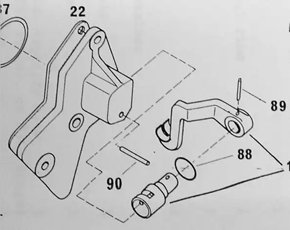
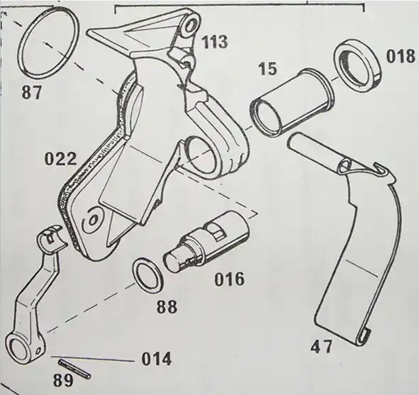
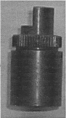
The New style bearing plate was the cure for some of the problems with the old style. It's housing was also made of magnesium, but it extends out and had a steel sleeve (see figure B, item 15) inserted into it to allow a new style cam (figure B, item 016) to rotate and not wear away the magnesium. It also was reconfigured to accept a case protector (figure B, item 47) to help protect it.
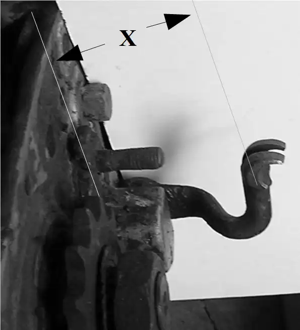
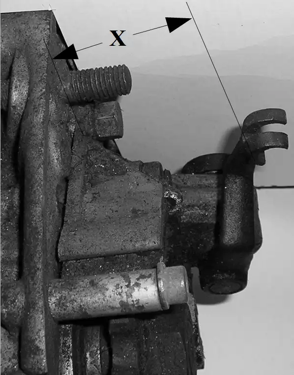
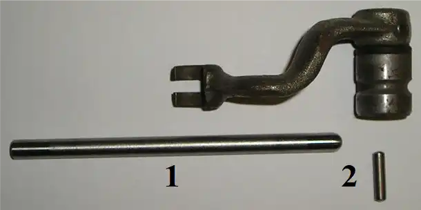
Both bearing plates have specifications that are indicated in the Penton and KTM owners manuals as “measurement X” (see figures C and D) that is required in order to have proper operation of the clutch in engaging and dis-engaging of the clutch plates when working on the clutch assembly. What is not mentioned in the owners manuals are some of the items that need to be looked at during maintenance checks of the bike and if you run out of adjustment on your clutch cable.
Because the KTM motors are used in dirt bikes, the clutch is used much more than that of street bikes and parts will wear especially after 20+ years. If your measurement “X” is less than specified or if you are overhauling your engine, remove the bearing plate and then remove the cam assembly (see figure E) for inspection. On the old style bearing plates you must remove the pin (Figure A, item 90) to remove the cam.
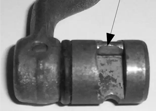
With the cam removed, check the pin (Figure E, item 3) for wear . If it is worn flat (see figure F) it must be replaced to reestablish measurement ”x”. A little bit of wear will put measurement “x” out of specs.. To replace the pin, you must remove the arm by driving out the pin holding it in place. With the arm removed a small hole needs to be drilled into the cam big enough for a thin punch to be inserted into it to drive out the worn pin. Insert a new pin (part no. 0402-041-550) and install a new o-ring (part no. 0770-021-120) before installing the arm back into place.
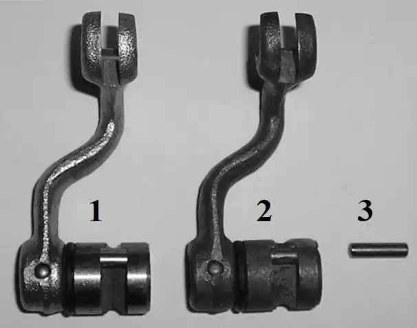
3 – new pressure pin.
Check the push rods for any deformity or wear and replace them if any is found.
The clutch plate assembly does not have any adjustment to it. As noted in the owners manuals, the center bolt on the clutch pressure plate (see figure H) is not for adjustment. It is a bearing surface for the push rod and if the bolt head has a hole worn into it from the push rod, it should be replaced (part no. 51-32-020-000). Not mentioned in any of the manuals or parts lists is the pressure plates came in a variety of thicknesses (see figure I) which is the method of compensating for the clutch plates stack to obtain the specifications for measurement “X”. If your measurement of the arm is less than “x” you need to install a thinner pressure plate. If your measurement is more than “x” you need to install a thicker pressure plate.
The pressure plates are made of magnesium and were all cast as the thicker plate. They were machined down to make them thinner and reduce the movement to the push rods to make contact with their center bolt.
#1 - push rod
#2 – pressure pin
Originally printed in the 2003 issue #19 of Still….Keeping Track
How do you identify a Sachs motor with a "stuffed" case?
The easiest way is with the cylinder removed. The opening between the case halves that the rod fits through is very narrow. Looking at it gives you the impression that there is no way that the cylinder can fit without the bottom of the sleeve hitting the cases.
Other ways to I.D. a stuffed case motor are:
- Check the serial number tag for - 1251/6B GS
- Predrilled holes in the cylinder fins for ISDT tag fastening.
- Larger diameter intake manifolds to accept 38 or 30mm Bing carbs. The smaller size Bing carbs will not fit.
- Motors from Monark bikes.
How do you identify a Sachs "D" cylinder?
Look for angled aluminum supports between the fins. Also, look for a "bolt-on" intake manifold.
What do you do if you removed the oil drain plug on a Sachs motor and the Aluminum case threads come out with it?
Permatex makes a re-threading compound that you apply to the bolt and case hole. You inset the bolt, let it set, unscrew the bolt, let the compound dry and you will have new threads to screw the bolt into. Those in the know will never try and remove the oil drain plug. They will remove the clutch case to drain the oil from their motors.
by Alan Buehner
Originally printed in the 2005 issue #26 of Still….Keeping Track
At the Penton Day at the AMA meeting on Feb. 5rh, Dane Leimbach talked about the Motoplat ignitions and some of the problems that can be expected from them. He gave some pointers on them and I thought it would be a good idea to share them with all of our POG members who could not make it to the meeting. This information pertains not only to the Motoplat ignitions, but also the new PVL and MZ-B ignitions.
KEEP THEM DRY
You know that old saying, "an ounce of prevention is worth a pound of trouble"? Well, water and moisture do not get along with ignition systems even if you have a sealed ignition cover. A hot motor and cold water will cause condensation to build up in the water tight compartment unless it is vented. Condensation causes corrosion to aluminum and magnesium and steel to rust. The best way to prevent corrosion after a day of muddy riding or after having just washed your bike is to remove the ignition cover and leave it off until the next time you go riding. This will allow any moisture to dry out.
flywheel removed showing mounting
plates and screws.
KEEP THEM GROUNDED
From time to time I get calls from people trying to get their newly acquired Penton to light up. I have shared information that I have learned from other people's stories. Such as, after painting the frame, remove the paint from the engine mounting tabs so the the motor will have good metal to metal contact with the frame. Make sure that the coil mount also has good metal to metal contact. Dane also shared this logical peice of information. All of the mounting points of the Motoplat lgnitons carry a ground and should be rust and corrosion free.
Since the Motoplat Ignition is mounted on a plate which is also screwed to the seal retaining plate ( on the KTM motors) removing and cleaning the mounting screws of the Motoplat will re-establish a good ground between the motor and the stator unit. This is especially important for all KTM motors. The magnesium motors corrode very easily. Over time the mounting screws will corrode and since the seal retaining plates have a gasket between it and the motor, it is the screws that are doing the grounding. This can be a big problem especially if the motor has been sitting for 20 years. In most cases, just removing the screws and retightening them is enough to reestablish the ground.
for stator unit used in the Penton
Sachs and KTM motors. It is attached
to the motor with 3 Phillips head
screws. The Stator is then attached
to the mounting plate with 3 pan
head screws.
DON'T KILL YOUR IGNITION
Never kick over a motor without the spark plug connected. Every time an electronic igitiop is spun, it builds up a charge in the internal capacitor that gets discharged when the spark plug fires. If the capacitor is not able to discharge it could overload to the point when it does finally discharge, it will burn out.
Examples of this given by "Speedy" Clasen (Canada) were: Removing the spark plug from the head and not having it plugged into the coil lead ., and resting against the cylinder while kicking the bike over, or drowning your bike in a river crossing, turning the bike upside down after removing the spark plug and turning the rear wheel to pump the water out of the cylinder. "Speedy" recommends keeping a piece of inner tube (rubber band) in your tool kit. If you should run into a situation where you need to pump water out of your motor, put the rubber band around the cylinder to hold the removed spark plug (connected to the coil) to the cylinder so that the capacitor can be discharged while the motor is being turned over. He has personally witnessed riders at river crossings unknowingly bum out their ignitions without realizing what they had done wrong.
the KTM motors only. It is held in
place by six Allen Head screws. The
Motoplat mounting plate attaches to
this plate with three Phillips head
screws.
What's The Difference?
by Alan Buehner
Originally printed in the 2004 issue #25 of Still….Keeping Track
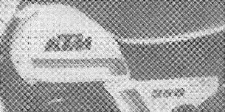
Since many of our member are expanding their vintage racing into "post vintage" and are looking for and restoring 1976 thru 1981 KTM built bikes, I am listing some photos of these bikes showing the style of gas tanks and what decals were used on them.
1976 MC-5
The fiberglas gas tanks were painted orange and came in one size that held 1.8 gallons.
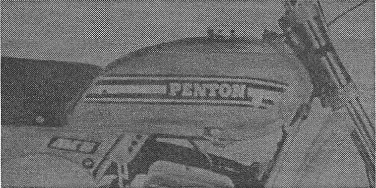
1977 GS-6
The fiberglas gas tanks were painted orange.. The 1977 models used a redesigned tank to fit the all new frame with the massive hi-breather backbone. It's tank is curved in the back by the seat which distinguishes it from the MC-5 tanks. The 125's & 175"s came with smaller 1.8 gallon tanks and used the same decals as the MC-5.
1977 MC-5
Fiberglas tanks were standard equipment and painted orange. They look the same as the GS-6 tanks except the tank is flat in the back by the seat and has a short extension sticking out. Fuel capacity is 1.8 gallons.
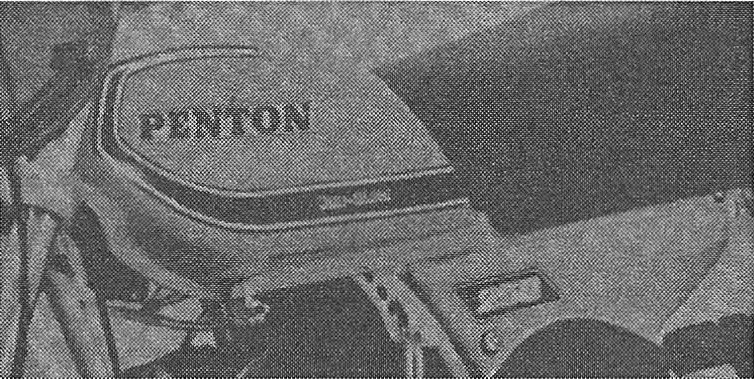
1978 MC-5 & GS-6
This was the last year for fiberglas tanks and they were painted white and redesigned. to fit the new 1978 MC-5 frame. The GS-6 tanks are curved in the back by the seat and the MC-5 tanks are flat.
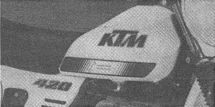
1979 MC-80 & GS-80
The plastic gas tanks were white. The moto cross bikes and 125 & 175 enduro bikes came with 1.8 gallon tanks. The 250,400, and 420 enduro bikes came with 3 gallon tanks.
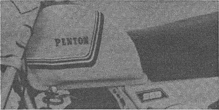
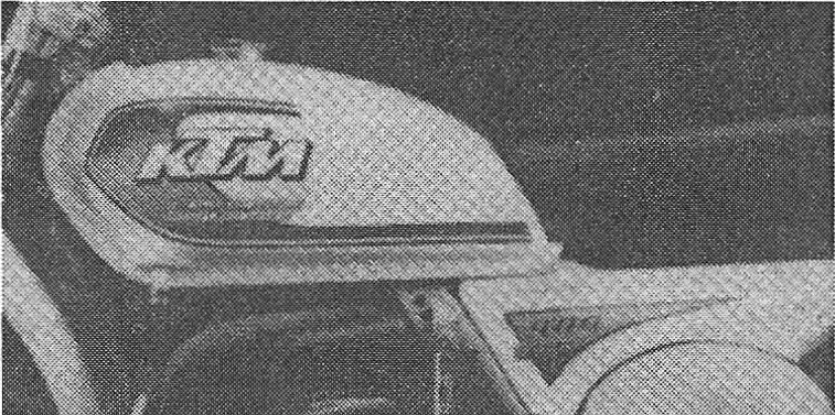
1980 MC & GS
The plastic gas tanks were white and redesigned with a distinctive hump at the gas cap. They came in 2 sizes, 8.3 and 10.3 liter capacities.
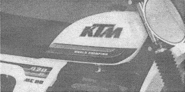
1981 MC & GS
The plastic gas tanks were white. They came in 3 sizes, 7.3, 8.3, and 10.3 liters. They are identical to the 1980 tanks except the 7.3 & 10.3 liter tanks used screw-on KTM plastic plates. The 8.3 liter tank used the KTM decal.
What's The Difference?
by Alan Buehner
Originally printed in the 2004 issue #24 of Still….Keeping Track
The purpose of this article is to provide information about parts on the Penton motorcycles in order to identify and know what the difference is. This should be especially helpful for anyone who has one or two Penton motorcycles and is not familiar with the models sold.
WHEELRIMS
There were 5 styles of rims that crune on the Penton Motorcycles:
Photo A - Radaelli "flat style"
Photo B - Radaelli "raised edge style"
Photo C - Akront
Photo D - Sun
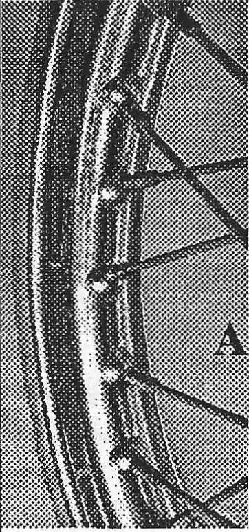
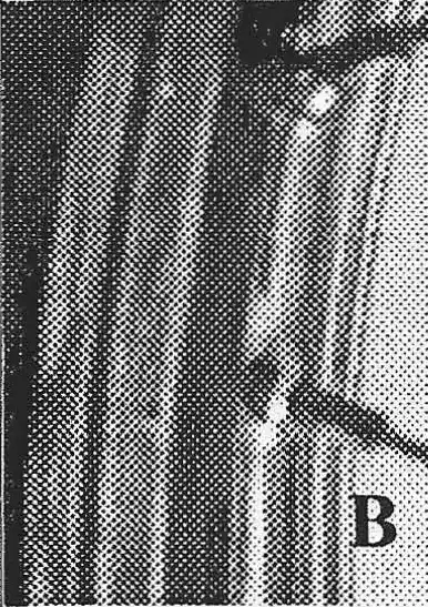
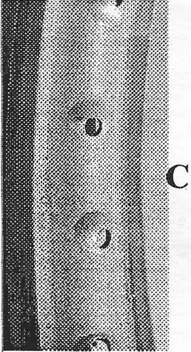
Not shown - Borrani (stamped on the rim) "raised edge" rims came on the first several shipments of 1968 Pentons. They were alloy rims with deep "mud catcher" edges.
The Radaelli "flat style" chromed steel rims came equipped on all the steel tank bikes from late 1968 thru 1971.
In 1972 the CMF bikes came equipped with stronger Radaelli "raised ridge style" chromed steel rims. These were used on the 100/ 125 bike up to 1975. They were used also on the 175 up until 1973.
The Akront alloy rims were first used on the 1973 250's which helped to lighten the bikes and with the "raised edges" made them strong. Akronts were equipped on all 1974 175 and 400's up until 1975. The problems encountered with the Akronts were mud build-up in between the raised edges.
The Sun alloy rims had a shoulderless design which eliminated the problem of mud build-up. They came equipped on the 1976 and 1977 MC5 bikes and the 1977 GS6 bikes.
REARHUBS
There were 4 types of rear hubs used during the life of the
Penton motorcycles.
Photo (unavailable)- straight with rectangular lugs
Photo J - straight with small round lugs
Photo E - straight with large round lugs
Photo F - conical
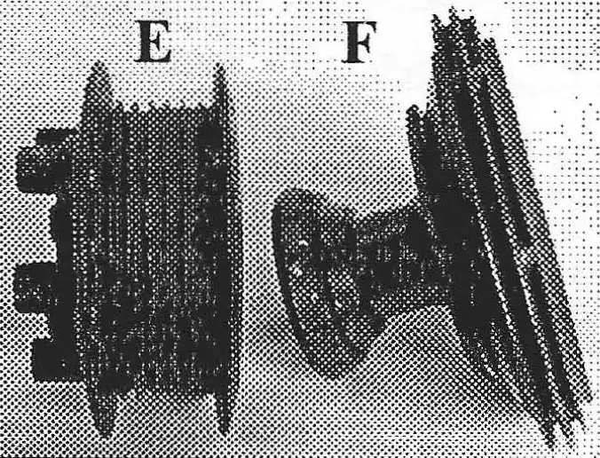
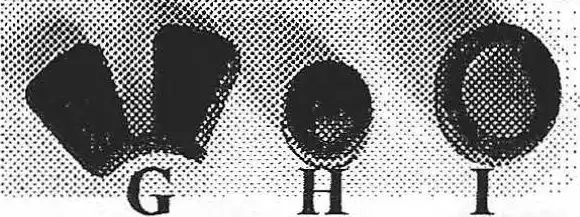
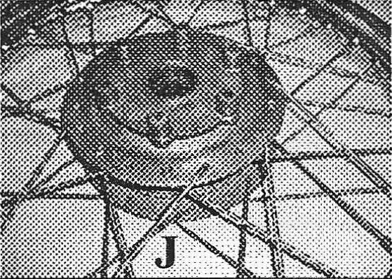
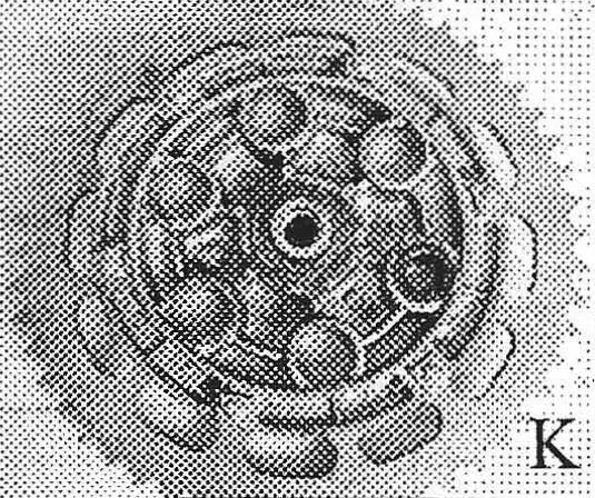
There were 2 styles of hubs, the straight which used a separate sprocket carrier (see photos E & J) and the conical (photo F) in which the sprocket was bolted directly to the hub. The straight styles had the advantage of being able to remove the rear wheel without having to remove the chain because the separate sprocket carrier (photo K) had it's own axle to attach it to the swing arm. Rubber shocks (photos G, H, & I) were used between the hub and sprocket carrier to cushion the impact from acceleration and give longer life to the chain and rear sprocket.
The very early 1968 model Pentons were the only bikes (approximately 300) to use the "butterfly style" rubber shocks (photo G). These were used with the hubs which had rectangular shaped lugs. The sprocket carrier was unique · that it only had 4 sprocket bolts. The design was not strong enough to withstand the power output of the Sachs engine which caused the lugs to crack and break. These hubs are very difficult to find because of this problem and it was only equipped for one year.
The later 1968 model Pentons were equipped with hubs with 6 small round lugs (photo J) and these used the small round rubber shocks (photo H) that fit inside the matching sprocket carrier (photo K). This set-up was used on all of the Sachs powered Pentons from late 1968 until 1974.
In 1972 the new 175 Jackpiners were equipped with the small size rubber cush drive assembly. However, the increased power output of the 175 would wear out the rubber shocks causing back and forth movement between the hub and sprocke carrier. If this "slop" was not repaired by replacing the rubbe shocks, the lugs on the hub would eventually be broken off. The fix for this problem was a new hub assembly which had large diruneter lugs (Photo E) and used the large size rubber shocks (photo I). This new set-up was used on the later 1973 Jackpiners and the 1974 & 75 lOO's and 125's when the supply of small size sprocket carriers ran out at the factory.
In 1973 the new 250 Hare Scramblers came equipped with conical rear hubs (photo F). This eliminated the cush drive set-up and breakage problem. Starting in 1974 all the 175's and then new 400's were also equipped with the conical rear hub.