Cerriani Fork Tube Nuts
What's the Difference
by Alan Buehner
Originally printed in the 2009 issue #42 of Still….Keeping Track
The purpose of this article is to show and explain the differences between the different fork tube nuts that were installed on the Cerianni forks - used on the Penton brand of motorcycles from the years 1968 thru 1975. These were used on the standard forks with the axles on the bottom of the fork legs (before the leading axle forks). The steel tank Pentons (1968 thru 1971) came equipped with the short 35mm Cerianni forks. The CMF 100, 125, & 175 Pentons (1972 thru 1973) came equipped with 32mm Cerianni forks. The 1973 thru 1975 CMF 250s & 400s and 1974 thru 1975 100, 125, & 175 Pentons came equipped with the long 35mm Cerianni forks. There is a difference between the short and long 35mm fork tube nuts.
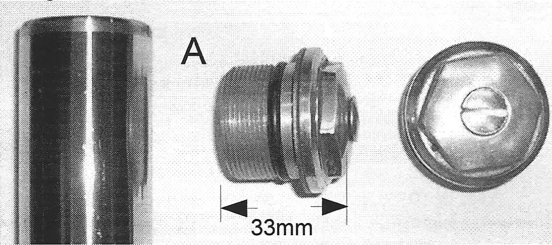
A. The early 1968 thru 1971 35mm fork tube nuts are short in length - measuring 33mm in overall height. The recessed area that goes into the fork tube measures 21 mm. The hex part measures 29mm.
The fork tube that is used with this nut is squared at the top and is secured in the top fork plate with the nut and is pinched with an alien head bolt in the top fork plate.
The Penton part number for this nut is #1-39-000.
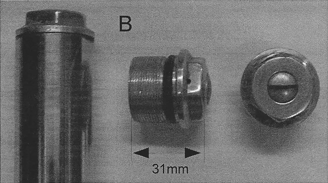
B. The 32mm fork tube nuts are short in length - measuring 31mm in overall height. The recessed area that goes into the fork tube measures 19mm. The hex part measures 24mm.
The fork tube that is used with this nut is squared at the top and is secured in the top fork plate with 2 alien head bolts that pinch it in the top fork plate.
The Penton part number for this nut is #1-503-021.
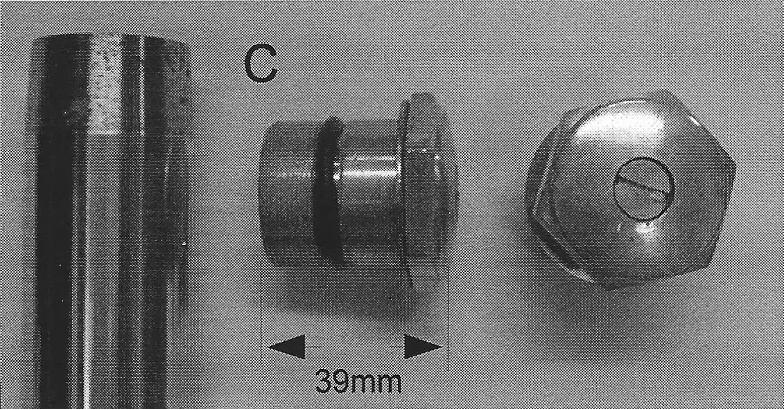
C. The 1973 thru 1975 35mm fork tube nuts are longer in length - measuring 39mm in overall height. The recessed area that goes into the fork tube measures 27mm. The hex part measures 29mm and is over sized, extending over the holes in the top fork plate.
The fork tube that is used with this nut is tapered at the top (as shown in photo) and is secured in the top fork plate by the nut which pulls it up tight into the top fork plate.
The Penton part number for this nut is #1-622-021
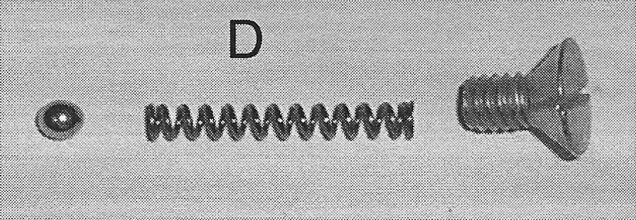
D. There is a vent system using a small pin hole in the bottom and a side hole exiting out the top side of the hex. A 4mm ball blocks the pin hole in the bottom and a spring applies pressure to the ball. A tapered screw secures the spring and ball. Excess pressure created in the fork tube is vented out through this valve set-up.
It is important to check that the ball and spring are not rusted out and that the side vent is not blocked by dirt. A non-functioning vent will cause oil to spray out of the fork seals.
What's the Difference?
by Alan Buehner
Originally printed in the 2008 issue #41 of Still….Keeping Track
The Penton motorcycles came equipped with Cerianni forks from 1968 thru 1976, after which they were equipped with Marzocchi forks.
The front axles used on these all look the same. They are fat on one end then taper down to slide through the wheel hubs. Looks are deceiving because the different sizes of forks used different lengths of axles. The purpose of this article is to show and identify the various axles.
Each axle shown is identified with the Penton/ KTM part number followed by the years, size, and brand of forks used and the measurements.
Refer to the POG "Tech Tips, What's the Difference? Front Forks" article in the Spring 2004 issue no. 22 newsletter. This shows and explains the different front forks used on the Penton/ Ktm motorcycles.
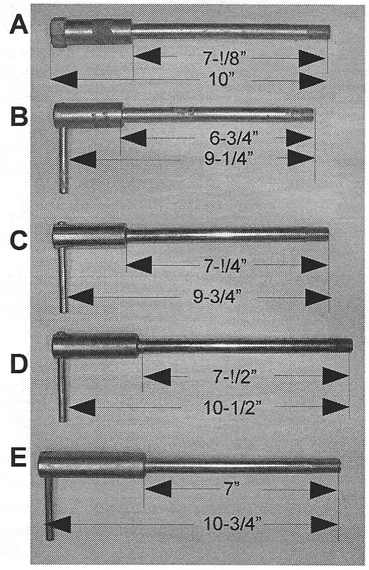
A. #6-35-000 front axle used on all the 1968-71 Penton motorcycles using the 35mm (short) Cerianni forks. The over-all length is 1 O" (255mm) with the thinnest part of the shaft being 7-1/8" (183mm) long.
B. #51-09-081-100 front axle used only on the early 1972 bikes equipped with the (baby) 32mm Cerianni forks. These forks have narrow fork plates that measure 6- 1/4" center to center for the fork tubes. The over-all length is 9-1/4" (235mm) with the thinnest part of the shaft being 6-3/4" (173mm) long.
C. #52-09-081-100 front axle used on the 1973-73 bikes equipped with the 32mm Cerianni forks (measuring 6-3/4" center to center on the fork tubes) and the 1973-76 bikes equipped with the 35mm Cerianni forks. The over-all length is 9-3/4" (248mm) with the thinnest part of the shaft being 7-1/4" (185mm) long.
D. #55-09-081-000 front axle used on the 1976-78 MC-5 and 1977-78 GS-6 bikes equipped with the 35mm Marzocchi forks. The over-all length is 10-1/2" (270mm) with the thinnest part of the shaft being 7-1/2" (193mm) long.
E. #55-09-081-100 front axle used on the 1979 KTM MC-80 bikes equipped with the 35 & 38mm Marzocchi PA ZTI A/S forks. The over-all length is 10-3/4" (270mm) with the thinnest part of the shaft being 7" (177mm) long.
by Alan Buehner
Originally printed in the 2008 issue #40 of Still….Keeping Track
Ted Landers called me a couple of months ago to order a new throttle cable for one of his KTM race bikes. During a race, his "bargain" throttle cable became frayed and caused the carb slide to be stuck in the wide open position. This caused the engine to high rev beyond the "red line". He instinctively hit the kill button, but it did nothing to kill the spark. His bike wound up exiting the track and taking off through the woods. The spectators found him laying on the ground and his bike laying on it's side a little further into the woods. Fortunately he and the bike came through that experience unscathed.
After talking to Ted, I thought about my own experience where I was at one of my trail riding areas in 1974. I had just kick-started my 72 Kawasaki 350 Bighorn when it started high-reeving all by itself. I turned the ignition key off but it just kept running. I panicked when the key didn't work and knew I had to make a quick decision as to what to do before the engine blew. So, I kicked it into l51 gear. Lucky for me, it pulled a big wheely and stalled out.
I always advise everyone to install a kill button on their bikes as a safety precaution. But there are situations where when an engine is red-lining that the current being produced by the magneto and being sent to the coil is so strong it cannot be grounded out by the kill buttons.
What would you do in this type of situation? Become superman and grab the spark plug wire and pull it off the spark plug? Every situation is different and it all depends upon what size engine it is you are dealing with. Is it inside a garage where you are starting your newly restored pride and joy - and failed to notice that the throttle slide was resting up too high because the new cable was too short or the set screw was turned in too much. Is it outside while you are riding, like in Ted Lander experience. Or is it like my case where you are outside and have restarted your bike. No matter what the situation is or where you are at, you need to know what to do and you need to do it fast. So, I contacted a few of our Penton experts and see what solutions they had to offer.
Al Born - Turn the choke on, up shift to a higher gear, and hit the brakes.
Doug Wilford - Turn the bike upside down (lay it down on the ignition side to prevent hitting the shifter). Put your foot or something over the end of the exhaust pipe. If you are riding, put on the brakes. Put the front wheel up against a large tree.
Do not pull the spark plug wire - this can knock you on your butt - it can ruin your ignition - the engine may still keep running after pulling the wire - it could cause a fire if the loose plug wire creates an arc.
Dane Leimbach - Put the bike into a high gear and hit the brakes to stall it out. The other option would be to pull the spark plug cap - this could hurt the ignition but would be better than having the engine self-destruct. There is the risk that in pulling the spark plug cap that the engine could still keep running if it develops a dieseling condition.
Bobby Lucas - Put the bike in a higher gear and get on the brakes to stall it. Put a shop rag into the exhaust end and turn off the gas. The last resort if you are riding would be to pull the clutch in and let the motor blow.
The following are tips from Dane Leimbach to prevent a throttle from sticking:
There are lots of issues that can cause throttle sticking, and I always make sure that it isn't going to happen. I can't remember the last time that I've had the stuck throttle.
The very first thing that you need to do before you start your engine, no matter if it is a brand new bike or one that is 40 years old, is to turn the throttle and close it, to see if the carburetor slide hits the bottom.If it doesn't, then don't even start it before you figure out what is wrong.
The second thing that I always do when I turn the throttle before starting the engine, is to make sure that there is a very small amount of slack in the cable. You need to be sure that there is some slack between the throttle and the carb slide, because when you turn the bars from one side to the other, and the cable gets bent a little more, it will tighten up the cable. Without some slack, you will be moving the slide up and down just by turning the bars from one side to the other.
If the slide doesn't hit the bottom of the carb when you turn the throttle close, then you need to find out why the cable isn't moving back easily. If you have a broken cable wire, that can cause some sticking. Sometimes, it's just a little kink in the cable and that needs to be straightened out so the cable moved smoothly in each direction.
All of this being said, you don't normally find the throttle sticking. However, in some carburetor designs, you can have an issue. Some of the older carburetor's idle screw, used to hit the bottom of the slide on the side of the slide. And over time, the idle screw can create a burr on the side. of the slide. A file can take the burr off the slide and fix the sticking problem.
The throttle position on the bars, can cause the throttle to stick too. If you don't have the throttle/grip just off the end of the bars, Then it can bind up the throttle and cause sticking.
I never put any lubrication on the bars under the throttle tube unless it is a silicone spray that actually dries out. If you have a moist lubrication, it can attract dust to the throttle which will cause dragging in the throttle. If you're in a muddy situation, as long as it's actually wet, then it won't stick. But when it starts drying out, then it will cause dragging.
by Alan Buehner
Originally printed in the 2008 issue #39 of Still….Keeping Track
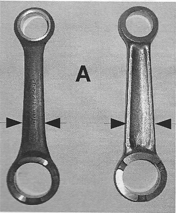
All rods for the Sachs engines are not created equal. As you can see in the top photo (A), the rod on the left is an original Sachs rod and the rod on the right is a reproduction rod. The reproduction rod is beefier with an "I" beam shape. They are both the same length eye to eye and the same thickness where the bearings insert. But, that is where the similarities stop.
The reproduction rod is wider from the lower bearing area up to the upper bearing area(as shown in photo A). Because of this, installing one of these new rods into a "B" or "D" Sachs engine will result in the rod hitting the inside of the right side engine case and will prevent the crank from turning. Note: This same rod is also used in the "A" engines. Because the diameter of the "A" crank is bigger than the "B" crank, there is plenty of room for the "A" rod to clear the inside engine case.
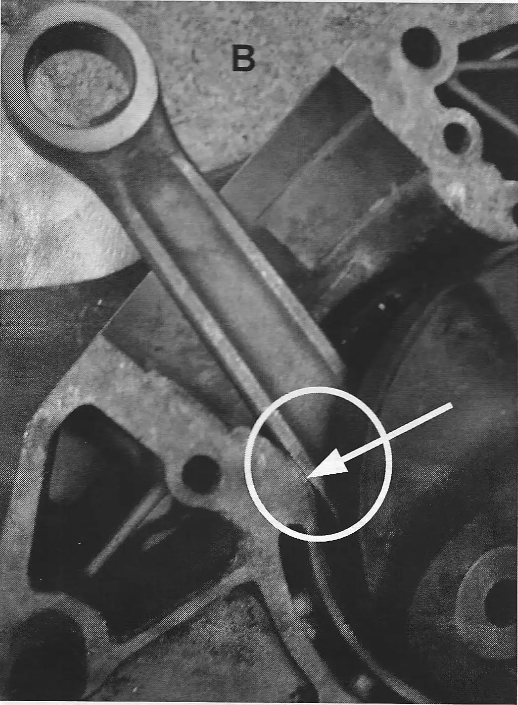
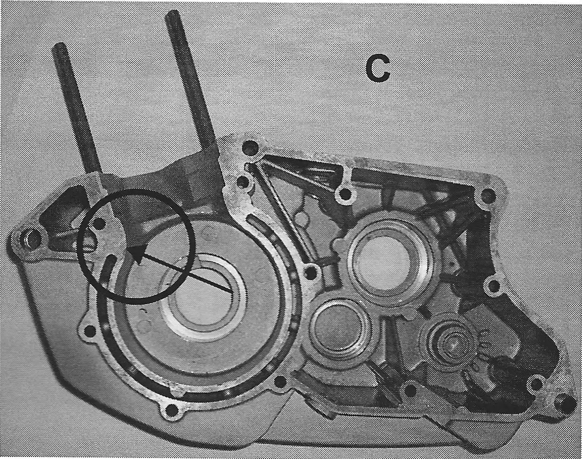
When installing any new rod kit in a "B" crank assembly, always check the rotation of the crank. Put the crank in the right side case, keep the wrist pin area centered, simulating its position with piston and cylinder, the rod will strike the forward end of the case (see circled area in photo B). Failure to check this can result in the crank locking up and you will have to re-split the cases. Note: movement of the rod will effect the right case half only.
If you encounter problems with the rod striking or hitting the inside case, the easiest way to handle this problem is to grind out the inside right case at the circled areas shown in photos B & C, to where there is suffient clearance for the crank to turn without the rod touching the cases (see circled area in photo B). Grinding out the cases will not affect the performance of your engine.
The hard way way to handle this problem is to remove the rod from the crank, and using the old rod as a guide, grind the lower part of the rod so that it matches the width of the old rod. Make sure the rod is thoroughly cleaned of any metal dust particles before pressing it back into the crank. Hopefully after re-installing the new rod, it will clear the inside cases and you will be good to go.
by Alan Buehner
Originally printed in the 2008 issue #38 of Still….Keeping Track
Our "experts" were on a "roll" back in December on the POG message board to help someone out on a problem that they were having. One thing let to another and a whole slew of "trade secrets" came out. I have copied them to this article to share this information with all of our POG members.
Carb access on Pen/KTMs is #%&@ tight. For quickest Bing jetting changes or float height settings, pull loose the fuel line, loosen the front carb clamp and rubber boot clamp, rotate 1/4 turn to the right ( away from pipe), pull the top two 7mm screws from the cap, pull the carb top loose just far enough to extend the spring and provide slack but not so far as to pull the slide and needle all the way out, then rotate the carb a full 90 degrees to the right. Working under the pipe from the bike's left side, you can pop loose the float bowl, replace jets, etc. When done, all can be put back in order in a couple of minutes.
If you do have reason to pull the slide & needle all the way out, most often the needle won't drop back into the needle jet easily, creating much frustration, swearing and Bingspletives. Far easier to pull the left side cover off, pull out the air cleaner, then stick your hand far into the airbox with long fingers down the carb throat, where you can get a digit or two on the needle with one hand while you urge the slide down with the other hand …usually goes right in that way and blood pressure gets back to normal.
-Jon McLean (OR)
Hi Jon, thanks for the tip, as a sidebar to re-centering the needle, I have had great success by removing the large throttle stop screw and insert a small piece of safety wire in thru the hole and wiggle the needle a bit, works so far on three different models … Adios,
-Tom Brosius
Hi Poggers, in keeping the "techshare" option alive, have the following: Small ISO vibe mounts for the clamp mounted VDO. McMaster-Carr p/n 9225K65, specs: M6x1 3/4in. height 1in. width (neoprene) male studs are 1/2 in. Adios, Penton Pals
-Tom Brosius
VDO illumination bulb BMW p/n 07119978279 $1.99 (12v2w) Adios Penton Pals.
-Tom Brosius
My tip is when dealing with rubber parts like the rubber shoes on the kick starter and the gear shift or the carb boot. Let the rubber soak in almost boiling water for about 10 seconds. This will make it very pliable and easy to install. They'll fit like socks on a rooster.
-Rod Whitman (Nebraska)
Was prepping to pull a head off of a 400 and came to one of the 13mm nuts on the head, got it off ok and then proceeded to lift the head off of the motor, now of course, the carb was not mounted …. off comes the head and one of the washers went flying off in the direction of the intake manifold ….. yipes, in a panic, I took a deep breath in hopes that I would find the washer sitting inside the intake manifold. I breathed another gasp and realized I positioned the piston at TDC ….. Visions of hysteria wreaked as I imagined if the washer fell into the bottom end. N Gawa Bwanna came out again (you stupid APE). As my luck continues, the washer was on top of the intake manifold, no harm done, prayed to the Penton God!. Better to be smart, than to be lucky; should have taped the intake manifold eh!
-Tom Brosius
I have a tech tip for that right out of "Ripley’s Believe It Or Not". I DID have a washer go into the bottom end once. Placing a small magnet inside the rod channel against one of the counter balances and slowly turning it. The foreign metal item came out 1st turn …. and then I inhaled a sigh of relief.
-Tom Benolkin
Ok Mr. Brosius! My PTT naturally (being from Arizona) involves heat baby-Yeah!, and the proper use of it. A small map or propane torch (they even have freon sized cans now), and a heat gun do wonders in persuading fork bushings, main bearings, rusty wheel bearings, races, and a host of other stubborn things that I have seen a lot of even "veteran" technicians struggle with. One of my guys at work the other day said the customer needs a new fork assy.-this one won't come apart. I asked did you try a little heat in the bushing area and, of course, he had never heard of heat in this application- (even with 30 years experience!).! went over and within 30 seconds had the fork apart unharmed. Of course you have to be careful where you use it (i.e. Magnesium, around fuel, contact cleaner, etc.-use common sense) but a little heat goes a long way sometimes.
If you heat your wheel bearing before attempting removal they are less likely to break apart leaving you with only an outer race to remove which can be a pain .. .I also use my heat gun a lot to heat up areas i'm putting seals in like countershaft and shift shaft seals-heat it up a bit and the seals slip right in.Also stickers,seat covers (i use a bit of heat gun to help stretch the covers),crusty old numbers can be removed from # plates in no time.Hope this helps somebody out there,someday!Happy Holidays to all my fellow POGGERS!!!Go Penton in
-Ric Emmal
If you've got a motor that's been sitting a long while and has become "one" try this. Head on down to Wally world or any such bargain store. Get one of the totes with a lid on it just big enough to set the motor in. Disassemble as much of the motor as you can, then set it in the tote, cover it with deisel fuel, put the lid on and let it soak [ totally submerge it]. Let it set for a week or so, then pull it out and drain out the fuel and see what's come loose. When you reach an impass, put it back in the fuel and let it soak some more. With a little patience you should be able to disassemble almost anything. I've managed to salvage more than a couple of motors this way. And as long as you keep the lid on, you can use the same fuel multiple times. try it, it works for me.
Recently completed the rebuild of a 78/400 motor …. testing the gearbox thru it's range, when shifting up to 6th and rotating the shafts, an instant bind occured within 1/3 rd. of c/s shaft rotation …… 6hrs later, after replacing one component one at a time, until I had the entire gearbox replaced, did I realize that human error could be a part of the problem …. .. As a lesson, I had 6th gear on the mainshaft upsidedown, which pushed the gear more towards the clutch side, that gear has a recess, that shoulda been facing outwards……
In recalling an episode from Super Hunky's book, he replaced an entire Can-Am motor for a friend, only to discover the pipe was plugged…… Moral to the story…… Humans find ways to complicate issues…. but Humans also find a way to fix them.
-Tom Brosius
I'spose this one does'nt really classify as a tech tip, but…. ….you can hear the ocean if you hold a MC5 airbox up to your ear.
-Bob Wardlow
Okay heres a tech tip for all you guys that don't put your bike away in September, when it gets "really cold out". Grind off the points of the ice screws before installing them in your tires. The rocks you hit in between ice patches and frost will less likely puncture your tube.
-Raymond
I've read several threads here on how to remove the needle bearings when they've started to become one with the swingarm. I went through the pain of removing the first one from my '74 400 by breaking the bearing ring and then gouging the cage away from the swingarm collar. After that little effort I wasn't looking forward to removing the second one.
But then I found a produce called Loctite Freeze & Release at the local hardware shop. Treating the bearing with this first and then using a washer & bolt puller - the bearing almost fell out.
So next time you face the enjoyable task of removing those pesky things, go get a can of this stuff and save yourself from inventing new swear words.
VMX1963
The Loctite part number is 996456…… it is a new product and some distributors dont know about it yet ….. BT
-Brian Taylor
Swingarm removal/bushing replacement (Six Day CMF):
- Swingarm bolt stuck to inner sleeve - with engine removed use a reciprocating saw to cut the sucker out. Make your first cut between the frame and swingarm. With the swingarm removed you may be able press/punch out the stuck bolt. If not, make next cuts between swingarm and rear engine mount. When cutting, stay away from the frame and engine mounts. I used a Bi-Metal, 6"-24tpi Recip Blade from Ace Hardware - PN # 2066422 and can verify that it is a very durable blade (8 cuts and still good). (When the swingarm bolt is stuck to the inner sleeve be careful and do not get to happy with a 12mm hex key and cheater bar. If the busing is really stuck, you will either strip the bolt threads, strip the socket head, or distort the frame. When you tum the bolt something is going to move or strip - don't ask)
- Bushing removal (rubber with inner and outer metal sleeves) - Option A: Beat and bang the old bushing out. Not recommended.
- Option B: Heat swingarm bushing area with propane torch (be careful and do bum down the house) until the rubber begins to bubble. Place punch on inner sleeve and knock it out. Next, take recip saw and make two longitudinal cuts 180 degrees apart. Be careful and do not cut into swingarm. Take cold chisel and punch/peel the sleeve out.
- Bushing Installation. - Put new bushing in freezer to cool. Clean swingarm bushing mounting area. I used a Dremel sanding drum on the ID to make nice and shiny. Heat swingarm bushing area with propane torch. Don't get too carried away, you are just trying to get a little expansion on the swingarm and a little contraction on the bushing to make things easier. Put a little grease on the cold bushing and install quickly. Have a bushing driver (proper sized socket will work) handy in case you need to persuade bushing into location.
Sheared / Broken bolt removal: I recently had the 3 stator plate bolts shear on my son's Six Day. Since they are small diameter (5mm) I was not sure how I was going to get them out. I found a Craftsman "Drill-out, Screw-Out" micro power extractors to be the ticket (pn 9 52157, cost $40). This kit (4 extractors) is for 3-6mm extraction. On one end is a reverse drill bit and the other end is an "ez out". On two of the three sheared bolts the reverse drill successfully backed out the bolts. On the third bolt I drilled the hole, flipped the tool and tried to remove bolt with the e-z out but no luck. Next, I douched with P-B Blaster/ Kroil - no luck. I applied a little heat - no luck. I repeated the process over the next several hours with no luck. I then drilled the bolt through and reapplied the penetrating oil - no luck. I added heat … I gave up. The next day I went out to the shop, installed the e-z out and the bolt came out!! Tip - don't get in a hurry, be sure and drill in the center of the bolt, do not break e-z out. Got any more tips?
-Ernie P.
by Alan Buehner
Originally printed in the 2007 issue #37 of Still….Keeping Track
At this year's ISDE event, one of the American riders was forced to call it quits on the first day with a mechanical breakdown. His wheel bearings wore out because they were never greased Yes, the modern bikes are very dependable, however, this rider learned a hard lesson that in competition, bike preparation is the rider's responsibility and he has no one to blame except himself when something goes wrong.
In talking to Paul Danik, who mentioned this incident to me, he stated that before the Six Days events that he rode in, he made it a point to completely tear down his bike and double check everything as he reassembled it. He also stated that all the other Penton riders made it a point to tear their bikes down before the event, even the bikes provided by KTM at the European events.
There are always lessons to be learned from mistakes when they happen and the best way to learn these lessons is from the "other guy's" mistakes.
Now that we are getting into the winter season, this is a good time for those of us who were running their bikes during the summer to take time and do some maintanence so your bike will be ready to go for the next riding season. The following is a check list by sections:
Cleaning (washing)
Before using a pressure washer Remove seat and gas tank. Tape off air intakes. Grease where possible as needed.
After Pressure Washing
Do the following maintenance before storing ….
Wheels
Repack the bearings - if worn, replace them - pack the new bearings.
Clean & grease the axles
Replace old worn out bolts & nuts. on rear chain tensioner.
Check the cush drive rubber for wear (used on lOO's, 125's, and early 175's.
chain & sprockets - check for wear & oil it.
Spokes & nipples - tighten but do not over tighten.
Rims - make sure they are true, check for cracks especially by spoke nipples.
Brake shoes - clean brake hubs. Check, clean & replace shoes if worn.
Backing Plates - clean & grease brake cam, check seals.
Swing Arm - remove the mounting bolt, clean & grease it. Check the bushings or bearings.
Front Forks - change fork oil, check brass bushings, seals & fork boots - replace any worn nuts & bolts,
Fork Tube Nuts - check o-rings, remove vent screw - check springs & balls - clean vent hole.
Steering Head Bearings - clean & regrease bearings & races, replace if cracked or worn.
Cables - check & replace if frayed. Lubricate them.
Control levers - check for cracks and wear - lubricate pivots.
Throttle - check for cracks and wear - lubricate if necessary.
Air Box - check for cracks & holes, clean & oil filter.
Air boot - check for cracks, holes, or other air leaks. Replace clamps if worn.
Gas Tank - drain tank for winter, check for any cracks - check petcocks - replace fuel lines if old or hard.
Coil - remove and check for any corrosion or rust between the mounting bracket and frame.
Frame - tighten every bolt & nut - replace if worn or rusty.
Sachs Engines
Change gear lube - do not use oil drain plug (removing this bolt will strip thread out of the case) - remove clutch case cover. With clutch cover off, pour in ¾ quart of transmission oil, then replace clutch cover.
Pull mag cover - inspect ignition to make sure that it is clean and dry. If you have a Bosch unit, remove flywheel - inspect for broken or loose magnets.
Tighten all case screws on engine Tighten engine mounting bolts.
KTM Engines
Change engine oil - replenish with 2 quarts of oil ( 1972-1978 models - other models refer to spec sheets).
Remove ignition cover - check Motoplat making sure it is clean & dry.
Drain crank area - remove small allen head screw under engine - then replace.
Tighten all case screws on engine.
Tighten engine mounting bolts - if bolts were extremally loose, check engine case holes for excess wear and cracking.
Inspect underside of engine and cases for corrosion - clean & paint to stop or prevent corrosion.
Carburetors
Remove float bowl to drain gas - check for visible wear on moving parts - clean bowl & reinstall.
Check for loose parts.
Exhaust Pipes
Remove end cap - look for excess 2 stroke residue build up in silencer and exhaust stinger. If there is excess amount of carbon build up, or wet sticky 2 stroke oil - remove pipe and burn it out.
Check pipe for cracks & repair
Check exhaust manifold springs - replace if worn - replace tabs for springs if worn.
Replace exhaust packing
What's the Difference?
by Alan Buehner
Originally printed in the 2007 issue #36 of Still….Keeping Track
This information was obtained from 1979, 1980, & 1982 KTM engine parts books. In as much that my collection of parts list is fairly complete and organized year by year I am confident that the information in this article is correct even though these are the only parts lists for these engines that I have. The information for this article was obtained by comparing the part numbers used in the 3 engine parts books.
new style bearing plate, clutch actuating lever, and
plastic ignition cover.
The 420 (type 560) KTM engine was introduced for the 1979 model year. It was the replacement for the KTM 400 (type 550) engine which was available from 1973 thru the end of 1979. The 420 was a brand new, totally redesigned engine. This became the blueprint for KTM's line of 2 stroke big-bore, air cooled engines which lasted 5 years until 1984. What is interesting is that KTM did not incorporate a reed valve into this new design. All the Japanese manufacturers were using this technology in their production engines and KTM did not embrace it until 1982 when it was used only on the 495 (NOTE: KTM started using reeds on their 1981 line of 125's and then on the 250's in 1982). The new 420 with it's piston port design, (from information I received from people who rode these bikes) was a rider friendly engine with plenty of power and a smooth predictable power band.
In 1980 the 495 (type 563) engine was introduced. Even though this engine was only a piston port design, it became known as the fastest production 2-stroke when Rod Bush did a speed test of 123.75 miles per hour with one in 1981(Dirt Bike magazine June 1981). This engine was wicked and fast.
Also, in 1980 the new 350 (type 561) and 390 (type 562) engines were introduced.
In 1982 the engine parts books shows only the 390 and 495. The 420 was apparently replaced by the 390. What is interesting is that even though the 420 is not listed in the 1982 engine parts book it is identified in the 1982 thru 1984 spare parts (frame) books.
Here's what my research has turned up for differences in these engines:
MOTOR CASES - They are all the same except for the 1982 495 was given a different part number because of a small change to the top, back part where the cylinder bolts down. This area was thickened to allow 2 transfer channels to be machined into the lower crank area.
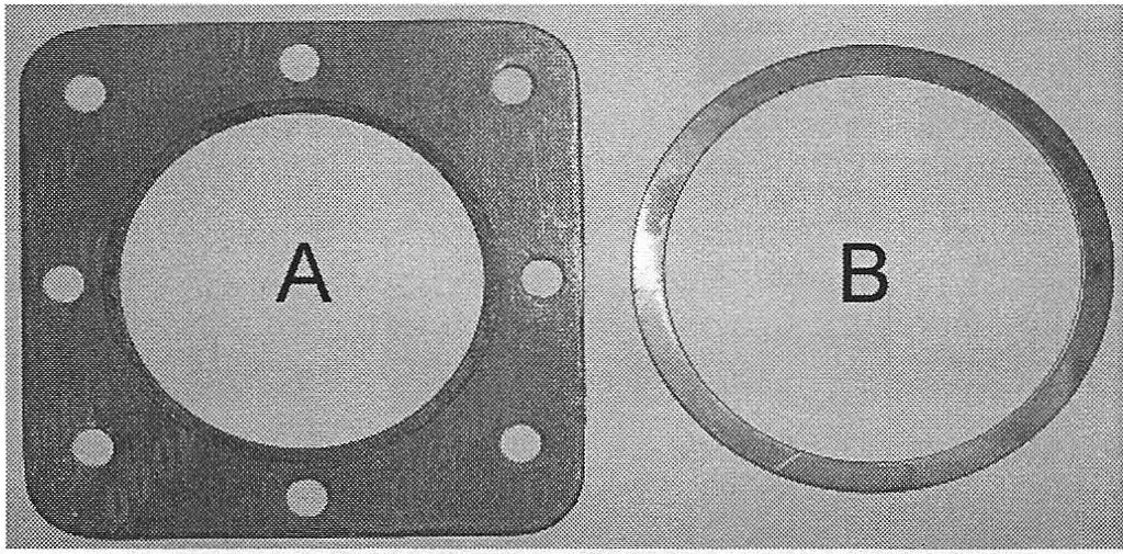
Since the cases are the same, the clutch case and center case gaskets are also the same with the exception of the 1982 495 center case gasket with it's added material to match the case change. The seals and O-rings are also the same.
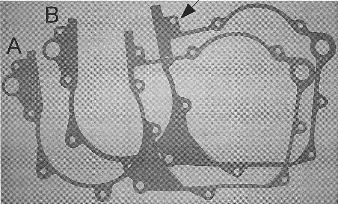
A - standard gasket
B - 1982 495 gasket with arrow pointing to change
INTAKE GASKETS - The 420 and 495 used the same intake gasket exept for the 82 495 which used the reed cage.
EXHAUST GASKETS - Only the 495, from 1980 thru 1984 used the same gasket. All the other models used a different size and were re-designed in 1980 and 1982.
BASE GASKETS - They are all the same except for the 1982 495 which was changed to match the cylinder redesigned with the reed valve. Base gaskets are of 4 thicknesses (0.2mm / 0.3mm / 0.5mm / & 1.0mm) to set the deck height of the cylinders.
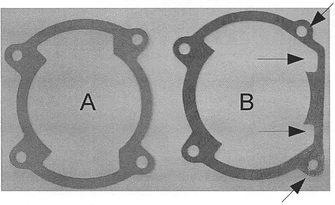
A - standard base gasket
B - 1982 495 base gasket, arrows showing changes
HEAD GASKETS - The 1979-80 420s used a round copper head gaskets (1 mm thick for the MC, a 2mm thick for the GS). The 350 used the old style 400 head gaskets. The 390 and 495 did not use head gaskets.
A - 350 head gasket
B - 1979-80 420 head gasket
CRANK ASSEMBLIES -All of these engines used the same crank assembly and used the M-30 crank bearings.
CLUTCH ASSEMBLIES - The 1979 and 1980 engines used the same clutch assemblies with a 81/21 tooth hub+ 29T pinion gear. In 1980 a 79/21 tooth hub+ 31T pinion gear was added which was used thru 1984.
COUNTERSHAFTS - the countershaft for 1979 thru 1984 are the same. They used the same gears except the 495 which in 1980 did not have a 1st gear, used a smaller diam. 2nd gear and a smaller (20T) 5th gear.
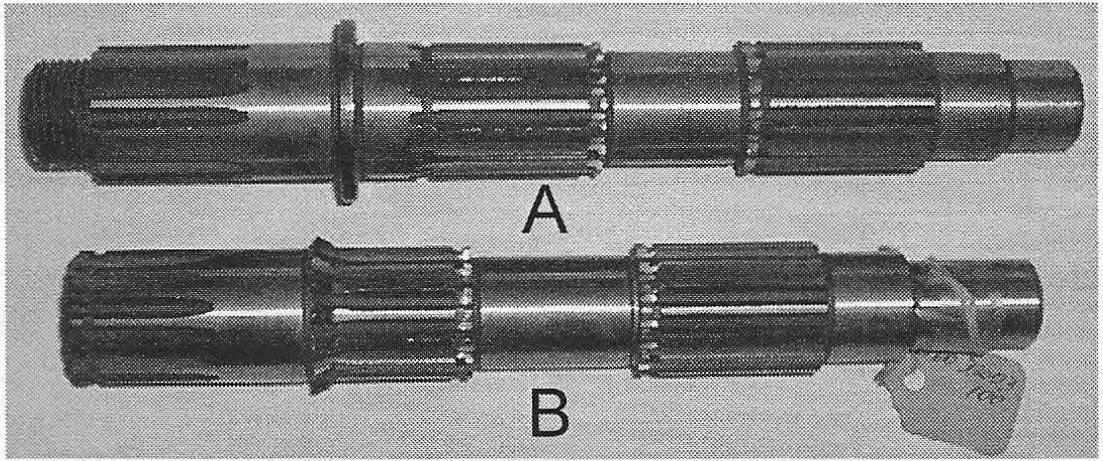
A - Old style countershaft used in 1972-79 KTM engines
B - Redesigned countershaf used in KTM 420/ 495 engines
MAINSHAFTS - The 1979 & 1980 420 (MC) used the same mainshaft. The 1980 420 (GS), 350, 390, & 495 used the same mainshaft. They all used the same gearing except the 495 which used a 16T 2nd gear. In 1982, the 390 and 420 mainshafts were identical, but redesigned from the previous years. The 390 and 495 (GS) used 5 speed gearing, the 495 (MC) used 4 speed gearing.
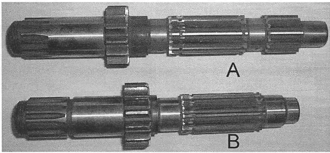
A - 1st generation mainshaft used in 1972-79 KTM engines
B - Redesigned mainshaft used in KTM 420/ 495 engines
BEARING PLATE - The bearing plate (clutch actuator) was redesigned for 1979 and made from plastic. In 1980 (thru 1984) it was modified by making it longer at the bottom, adding an extra fastener hole and changing the hole where the countershaft seal fits into, to prevent the seal being pushed too far in towards the engine. The bearing plate gasket in 1980 was also redesigned to fit to the changes made to the bearing plate.
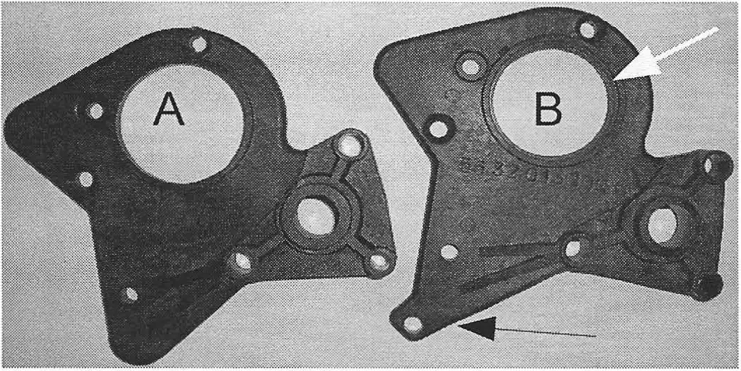
A - Bearing plate use on 1979 420 engines
B - Redesigned bearing plate, arrows showing changes
What's the Difference?
by Alan Buehner
Originally printed in the 2006 issue #35 of Still….Keeping Track
The purpose of this acticle is to show and explain the differences between the 2 sizes of cush drives and their parts used on the 1972 thru 1975 Penton 100 & 125s, and the 1972 thru 1973 Penton 175s.
The small size cush drives were used on all the 1972 model year bikes. This worked fine for the 100s and 125s but the 175s had too much power for small cush drives to handle. When the cush drive rubbers wore to the point where there was back and forth play between the sprocket backing plate and the hub, the torque from the 175s would shear off the tits of the hub.
The fix for this problem was 2 fold. The
first was to increase the diameter size of cush drive rubber. The second was to remove the cush drive units from the 175s in 1974 and bolt the sprockets
directly to the rear hub as was done with the 250s when they were developed in 1973.
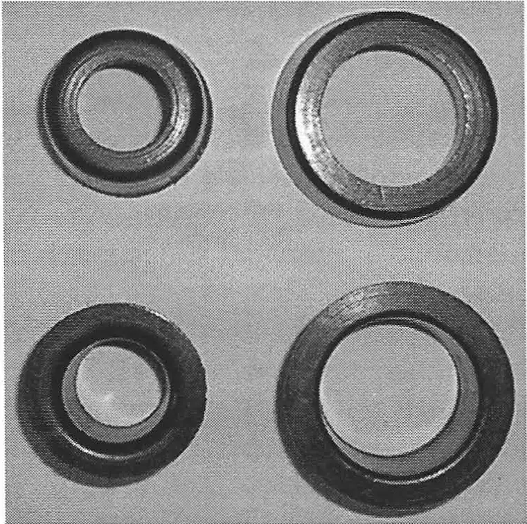
The sprocket carriers show the most obvious difference which is the I.D. for the 6 cush drive rubbers. But, there are 2 other differences.
The first is the center hole for the bearings. The New Style carriers use larger diameter bearings to deal with the stress applied to them by the engines. (Note: the bearings in the sprocket carriers will wear out faster than the rear hub bearings).
The second difference on the sprocket carriers is the thickness along the outside edge. The 100s and 125s use 428 sprockets and the 175s used 530 sprockets. The 530s are thicker than the 428s and to compensate for this, all the 17 5 sprocket carriers were milled down to keep the rear sprocket in line with the drive sprocket.
The axles are different as can be seen with the new style being a 2-step for the two different bearings.
The snap rings are different diameters to fit the openings in the carriers.
The larger cush drives were developed by 1973 to fix the 175 problem. The larger units were put on the 1974 production year bikes (100s and 125s) as soon as the supply of small cush drive units ran low. As a result, it helps to know the difference when restoring and repairing these bikes so one knows which unit that they have and what parts are needed.
The most obvious is the cush drive rubbers. The small size measure 23-26mm O.D., the large size measure 32-34.5mm O.D. If you can put your index finger through it, you have a large size cush drive.
The following is an explanation of what some of the other differences are:
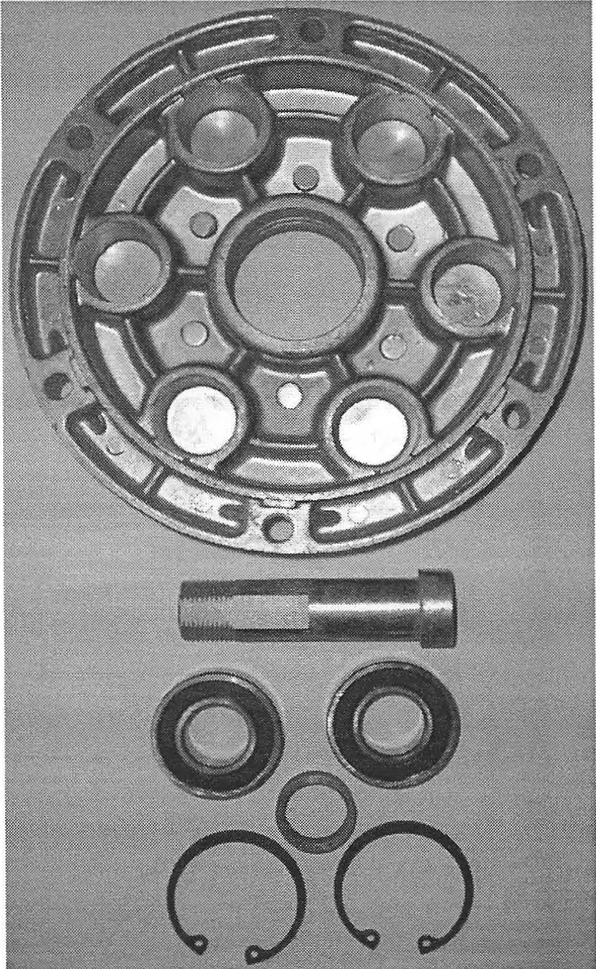
specifications
Carrier #51-10-050-000 for 100/125
Carrier #52-10-050-000 for 175
Axle #51-10-054-100 85mm long
bearings #0625-060-043 size 6004
spacer #51-10-057-000 8mm wide
snap rings #0472-421-750 42mm diam
drive rubber #51-10-059-000 small size
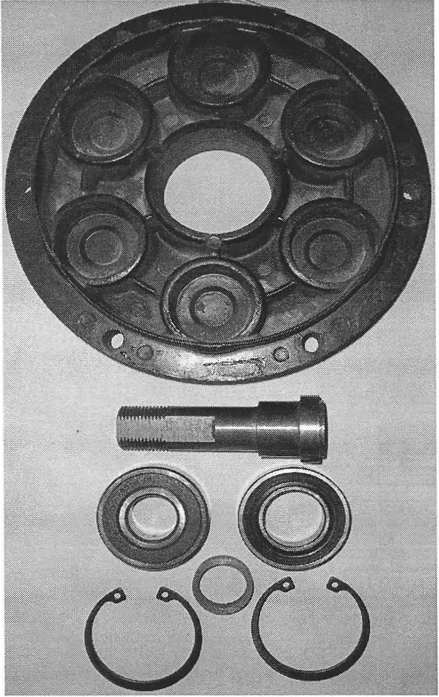
specifications
Carrier #51-10-050-300 for 100/125
Carrier #52-10-050-300 for 175
Axle#51-10-054-300 85mm long
bearing #0625-062-043 size 6204
bearing #0625-060-053 size 6005
spacer #51-10-057-000 8mm wide
snap rings #0472-471-750 47mm diam
drive rubber#51-10-059-300 large size
by Doug Wilford
Originally printed in the 2007 issue #34 of Still….Keeping Track
Thirty-nine years ago V-001 rolled off the assembly line. Would you believe the topic about the Sachs shifting problems has not changed in that many years. Considering all the modifications and changes made inside the Sachs transmission. I still hear the same bad mouth. Kind of like the 250 pound 125cc rider that says: “I need more power”. Just maybe, there is a solution other than mechanical.
The statement of: “It is impossible to miss a shift” is correct when done properly, if adjusted properly and the selector key is not worn out. Sachs, Zundapp and some others use what is called a “Draw Key” shifting mechanism.
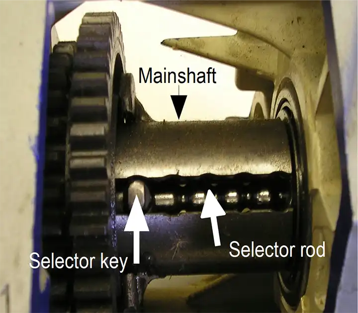
Draw Key: All the gears in the transmission are in a constant mesh with each other. The main shaft has the sprocket attached to one end. The gears on the main shaft are free and spinning on the main shaft. Inside the main shaft is the selector rod, which has the selector key attached, when shifted, the key moves from one gear to the other locking the engaged gear to the main shaft and the (Christmas Tree) lay shaft.
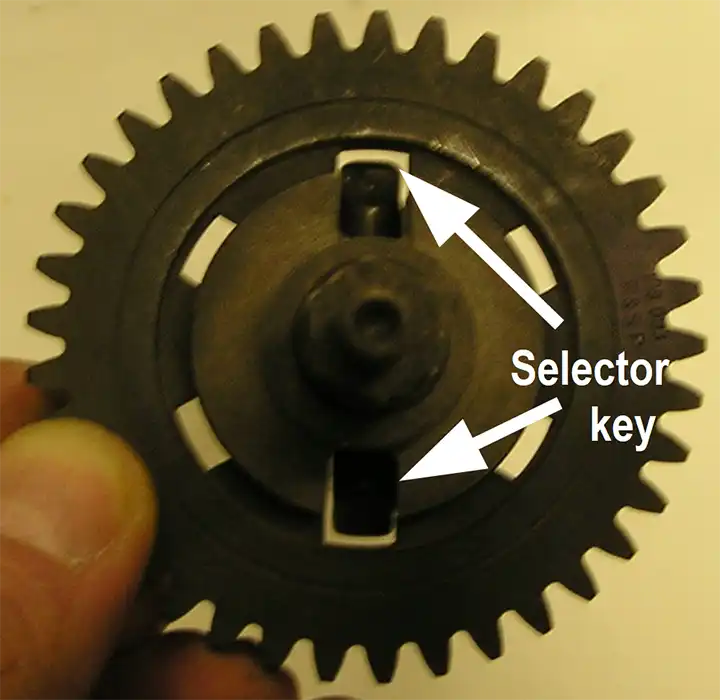
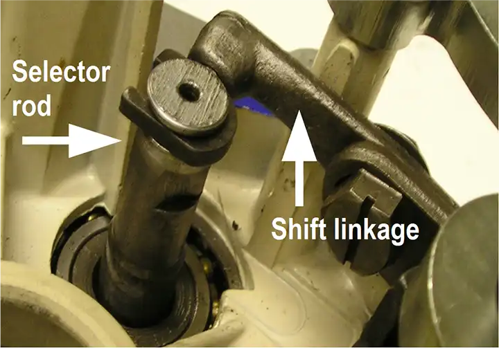
The lay shaft has the clutch hub attached. Adjustment is made to the keys position by using the selector assembly. If properly adjusted, the key cannot go any farther in or out of the gear it is lined up with. The selector rod has detent grooves that help locate the key for perfect alignment. The “Draw Key”, “Key”, or selector key is what you control with your foot on or under the shift lever.
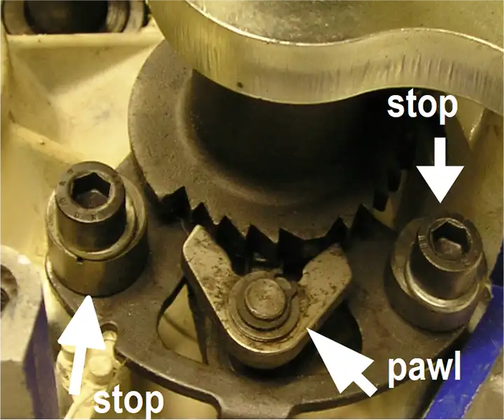
Most other motorcycles use a “Drum” or Fork shifting system. Remember now, these are two different shifting systems. This makes two different ways to properly shift gears. German engineering makes the draw key act more like an old BMW (Push down or Pull up) where you hold the shift lever against the stop until the gear is engaged.
Most of us have ridden Japanese bikes that rarely miss a shift no matter how you operate the shift lever. Stomp on it, tap it, whatever, and you get the gear you are after.
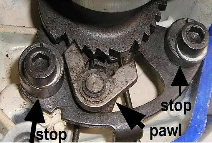
You cannot under any circumstance tap or stomp the Sachs shift lever and expect the Draw Key shifter to work properly. By holding the shift lever against the up or down stop, it cannot go between gears and stay there. This is why you miss far fewer gears up shifting than down shifting. It takes practice to fan the shift lever up, compared to tapping or fanning it on a down shift. Most of the time you will miss, going down from 3rd to 2nd, ending up in neutral. How can this happen? Neutral is beyond second, in between 1st and 2nd.
Experience is a great teacher. After many hours repairing transmissions on the work bench and many hours in the saddle, I learned that when you stomp, tap or fan the lever down, the selector key has a tendency to fly or go right thru the lower gear you were after. This is the easiest, biggest and most often misuse to the Draw Key system. Try it in practice. Educate your left foot. Shift positive. Hold the lever against the stop! YOU MUST HOLD THE SHIFT LEVER AGAINST THE STOP!
Break the habit, educate your left foot, think Penton and most of all, “Have Fun.”
Foot Note: For the proper length of shift lever: a bigger foot = a longer lever. The length of the lever controls the distance you have to move the lever up or down.
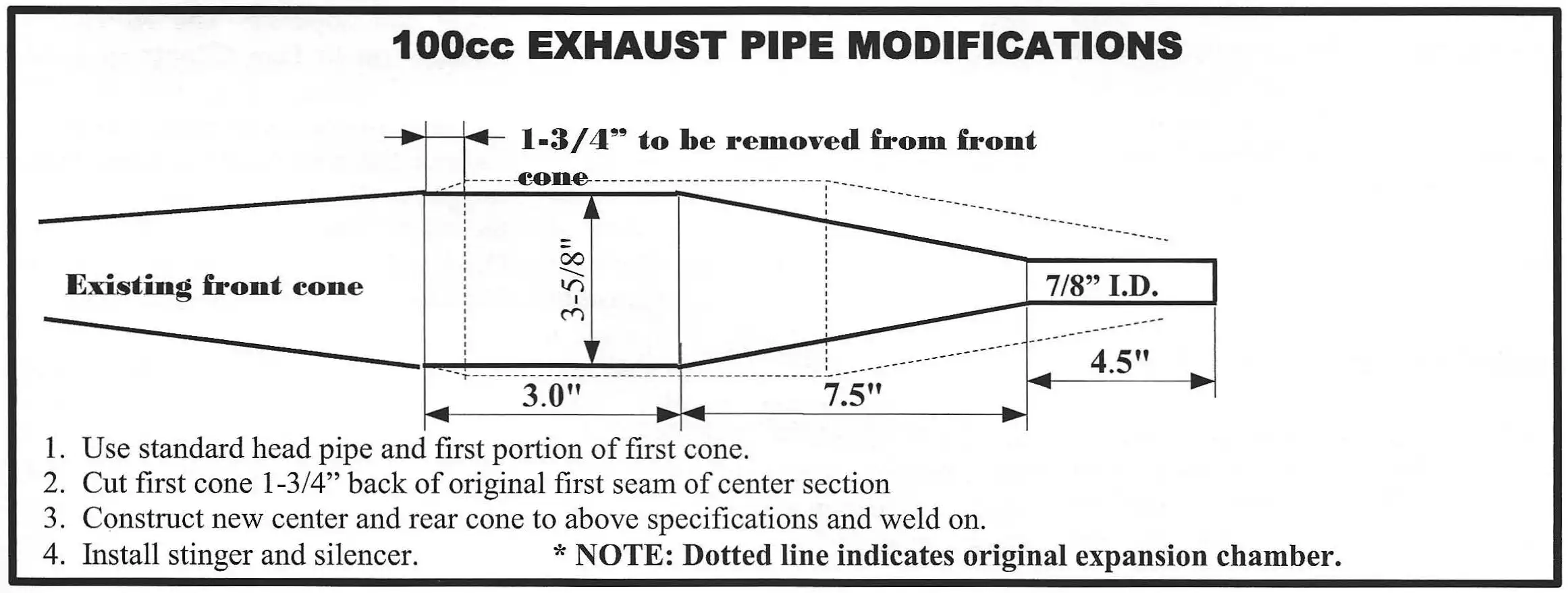
for 100 and 125cc Sachs Cylinders
Originally printed in the 2006 issue #33 of Still….Keeping Track
The following information is reproduced from a letter dated February 26, 1973 from Carl Cranke who was Service Manager at Penton West in California. The cover letter, diagrams, and instructions were provided to me by Victor Monz (CA). A METTCO dyno chart (not shown) was also included which shows 19.0 horsepower at 8,000 RPM after modification for a 100cc Penton.
- Alan Buehner
February 26, 1973
Gentlemen:
The following are modifications that we have found to be advantageous in track and moto-cross competition. Bear in mind they are strictly experimental and there are no guaranteed results due to the many variables involved. If performed in an accurate and workmanship like manner, we are sure you will realize good results. After modification we have found the engines reasonably reliable but remember - nothing is free - the price you pay will be longevity.
Carl Cranke, Service Manager
PORT DIMENSIONS FOR 100 AND 125cc
- Grind cylinder to dimensions shown on
drawing. - Cut 2mm from inlet side of piston skirt.
- Grind inlet spigot to 28mm diameter and blend
into port - Machine cylinder head .050 and re-contour
squish band to 48.0mm for 100cc and 54.0mm
for 125cc at a 14 degree angle - Chamfer all port edges with a smooth radius.
- We use a 27mm Bing on the 100cc
135 Main Jet
2.76 Needle Jet
35 Pilot Jet - We use the new 28mm Bing on the 125cc
140 - 145 Main Jet
2.76 Needle Jet
35 or 40 Pilot Jet - On the 125cc we use the standard exhaust pipe with the rear shielding cut off and a silencer installed on the existing stinger.