

Lectron Carbs
by Alan Buehner
Originally printed in issue #52 of Still….Keeping Track
Lectron Carburetors came out in the late 70's and were installed on the 1977 Penton 175 MC-5's with the size 36 mm carb. They were available as an aftermarket accessory in the Hi-Point catalogs starting in 1977 and were available for many different brands of bikes. They were available in 30, 32, 34, 36, 38, & 40 mm sizes. The size number is marked on the side of the carb.
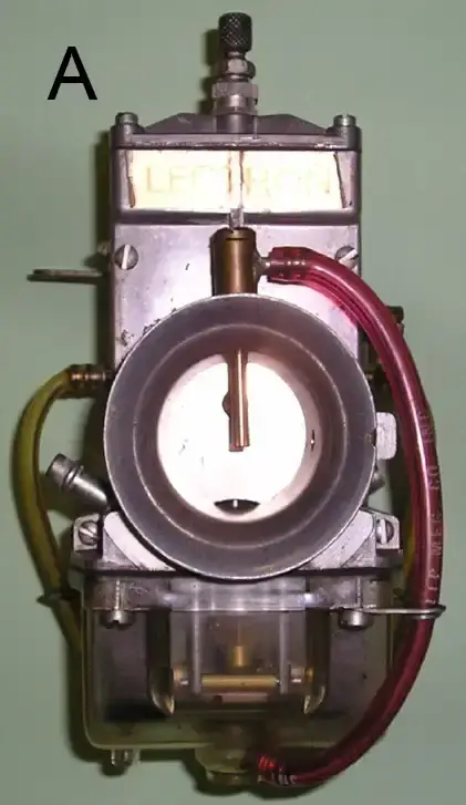
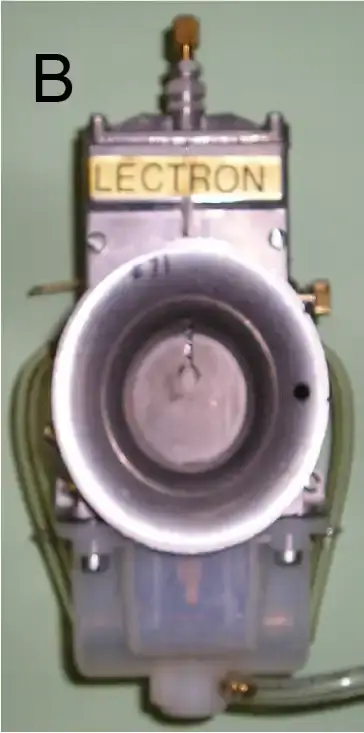
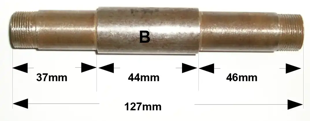
Although the carbs were available in assorted sizes, the body of the carbs were all the same. The main difference is the the center bore which determines the size. The other difference would be the outside diameter of the intake bell (see photo of carbs A & B) and the the intake mount. These were milled down to fit the different brands of bikes. The Penton bikes use the Lectrons with the largest intake bell (see photo B).
Lectrons were available in 2 styles, the regular and the Power Jet.
The Power Jet has a nozzle inserted down into the intake bell of the carb which has a fuel line connecting it to the bottom of the float bowl. As the throttle slide is opening, the velocity of the air coming into the carb creates a suction that pulls extra fuel into the carb through the nozzle.
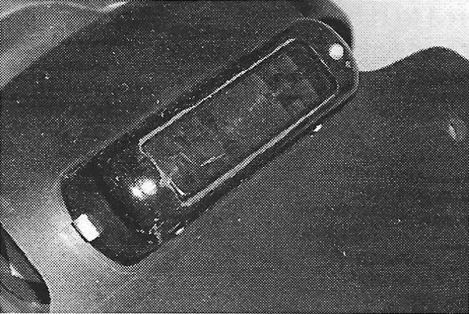
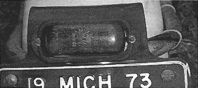
FLOAT BOWLS
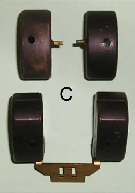
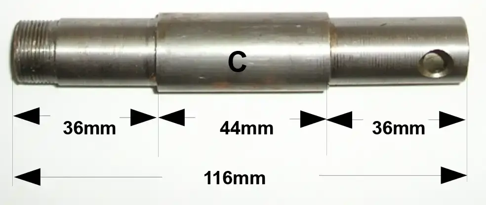
The original Lectrons came with clear float bowls (as shown in photo A of Power Jet) that had 2 posts coming up from the bottom that 2 independent floats (see photo C) slid up and down on. These were very durable and worked well until leaded gasoline was abolished and gasoline with ethanol (alcohol) was introduced. Alcohol will cause the clear float bowls to soften and distort. This in turn causes the 2 post to move and will affect the movement of the floats. The fix for this problem was the opaque float bowl (as shown in the photo B of the regular Lectron carb). The opaque float bowls do not have the 2 posts in them and require a replacement single unit float (see above photo C).
There were 2 styles of float bowls. The regular style and the Power Jet style. The Power Jet style has a brass connector inserted at the bottom of the bowl to which a thin fuel line is attached (see photo A - Power Jet carb). Both style of bowls are available in the opaque, alcohol proof type.
SLIDES
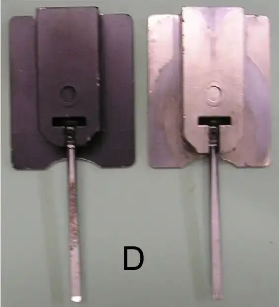
The Lectron slides are made of aluminum and hold the special needles that determine the fuel and air-metering. The original slides were painted black. These were upgraded later with chrome plating (see photo D). The purpose of these coatings is to prevent the slides from sticking open when under power. Over time and use, both coatings will wear off. If you encounter a sticking slide while riding a bike with a Lectron, the fix will be to remove the slide, clean it and spray it with primer paint. Allow the paint to thoroughly dry (recommended 24 hour waiting time) before installing it.
NEEDLES
The Lectron needles are the secret to the Lectron carbs and do away with the different jets and parts found in conventional carbs. The needles are precision ground with a flat side. The length of the needle and it's cut determine the main jet size and mid range fuel delivery. Fine tune adjustments are made by turning the rod in or out of the slide. The needles are threaded at the top to allow this adjustment. The needles are identified with a 2 digit number painted on the round side.
What's the Difference?
By Alan Buehner and “Chicago” Jerry Grakauskas
Photos by “Chicago” Jerry Grakauskas
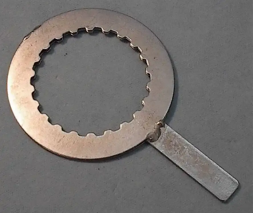
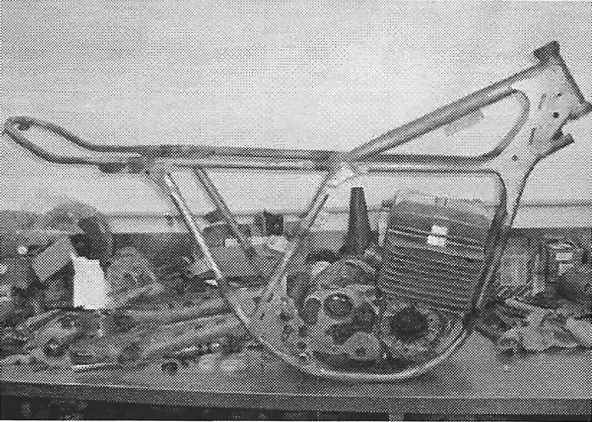
Just when you think that you know it all, something comes up to make you shake your head. I always knew that there were 2 types of 175 cranks. One for the “black” engines and one for the “silver” engines. “Chicago” Jerry informed me a couple of months ago that he has encountered a third type of 175 crank which is where these photos came from and why this article was written. He is quite certain that the newly discovered crank size came from the factory that way. It was not a conglomeration of mixed parts. He has three of them that are identical.
Now there is a possibility that this third type came about because someone screwed up the mag side threads and exchanged the crank half, but, anyone that is going to be dealing with rebuilding a Jackpiner engine needs to know what is out there and be ready to expect some problems. This article should help you deal with it.
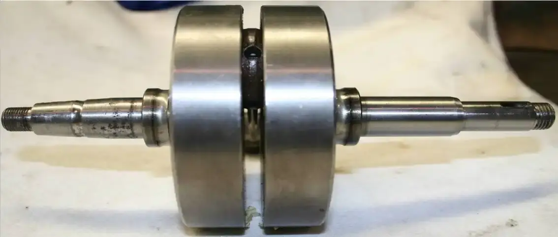
Both shafts measure 20mm in diameter. Photo shows the inner races of the crank bearings in place.
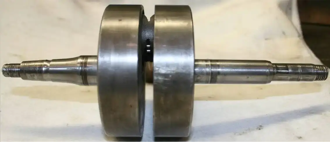
Both shafts measure 25mm in diameter.
Note that the right shaft is straight and then tapers down.
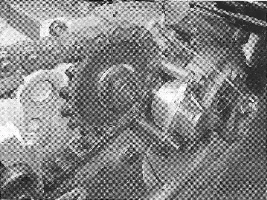
The first photo (A) shows the crank from a 1972 “Black” engine with the same small diameter shaft on both sides requiring two m-20 (small) three piece bearings that measure 20mm I.D. X 52mm O.D.
Both shafts measure 20mm in diameter.
The corresponding small seals are as follows:
The ignition side measures 20 x 30 x 7 mm .
The part number is #0760-203-070.
The primary side measures 20 x 35 x 10 mm.
The part number is #0760-203-510.
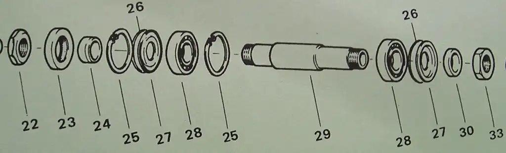
The second photo (B) shows a crank from a “silver” engine with the magneto side (left side in photo) being large and requiring a L-25 bearing but it still has a smaller clutch side (right side in photo) half requiring a M-20 bearing.
The corresponding seals are as follows:
the ignition side measures 25 x 35 x 7 mm
The part number is #0760-253-570.
The primary side measures 20 x 35 x 10 mm.
The part number is #0760-203-510.
NOTE: If you have one of these cranks, make sure that you measure the mag seal after removing it.
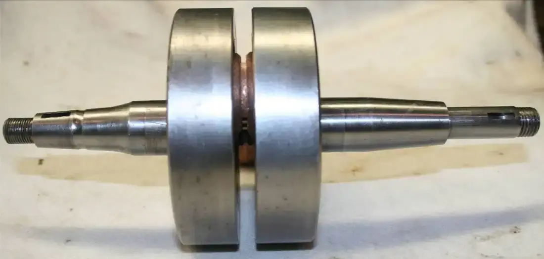
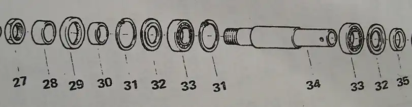
The third photo (C) shows the crank with the same larger diameter shaft on both sides, requiring two L-25 three piece bearings that measure 25mm I.D. X 52mm O.D.
Both shafts measure 25mm in diameter.
The corresponding seals are as follows:
the ignition side measures 25 x 35 x 7 mm
the primary side measures 25 x 35 x 7 mm.
The part number for both is #0760-253-570.
by Alan Buehner
Photos by Kip Kern
Originally printed in the 2011 issue #50 of Still….Keeping Track
In the last newsletter, I showed and explained how you can make some of the “hard to find” special tools that are needed to perform repairs and maintenance on the Sachs and KTM engines. Since then, I have talked to Kip Kern and these are some of the tools that he has bought or made to work on Sachs and KTM engines.
Sachs M-20 bearing outer race puller. This is a large blind bearing puller that can be purchased from a bearing supply house (such as Applied Industrial). The tool is inserted behind the lip of the race then bolt is screwed in to expand the fingers of the tool. Engine case is heated, placed in a press upside down and then tool is pushed out of the bottom of the case..
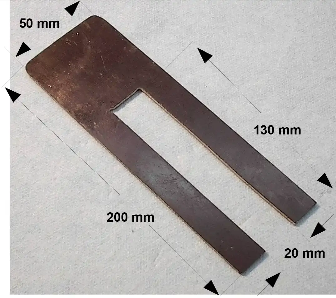
KTM clutch basket holder. If you know how to weld, then this is an easy tool to make. Kip uses 2 old clutch plates, slides them over an inner clutch hub (to keep them lined up) and welds them together, then welds a handle onto them. The handle should be approx. 18mm wide so that it will fit between the fingers of the clutch basket
Piston rest to install all cylinders. This can be made out of plywood or sheet steel and is placed under the piston to hold the piston steady. This frees up your hands to allow you to slide the cylinder down over the piston while you squeeze the piston rings. (Sachs M427 manual)
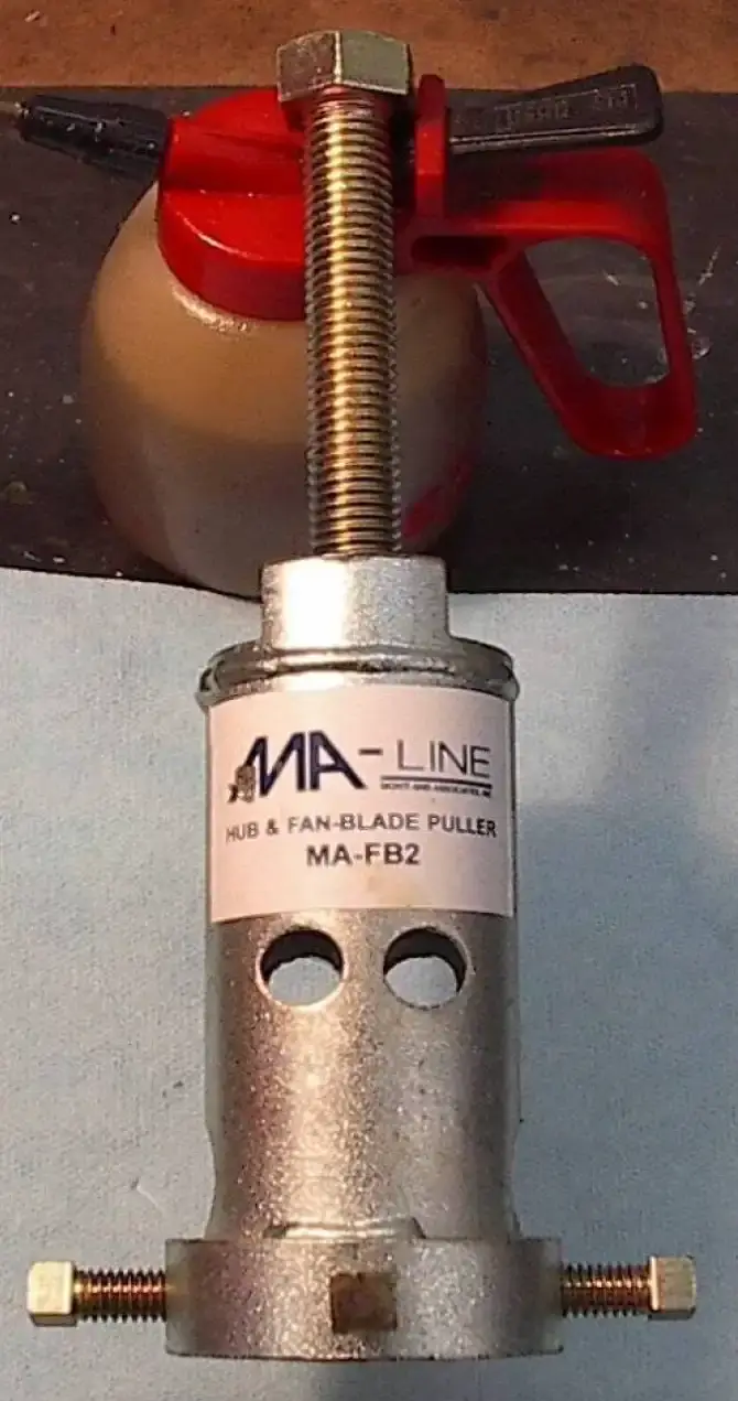
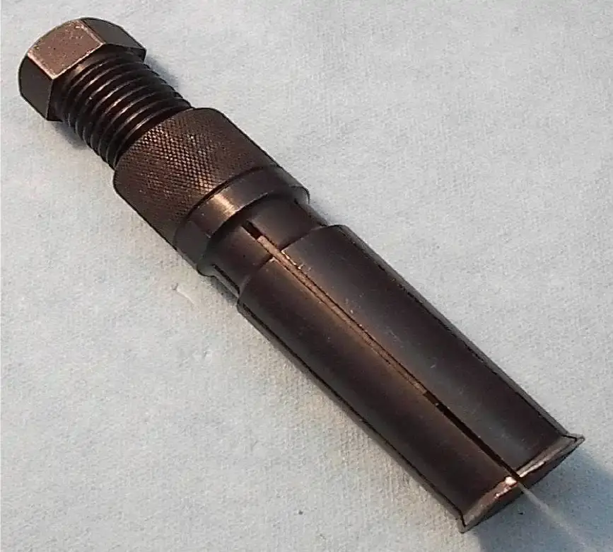
KTM/Sachs crank bearing inner race puller that can be used to pull the inner races of the 3 piece crank bearings off of the end of the Sachs and KTM cranks. This is an air conditioning fan blade puller that can be purchased at your local heating and air conditioning supplier. It is made by MA-Line – part no. MA-FB2. Kip machined 1/16” off the bottom of his puller to allow some extra play, to center the screws into the groove of the inner race.
HOME MADE KTM TOOLS
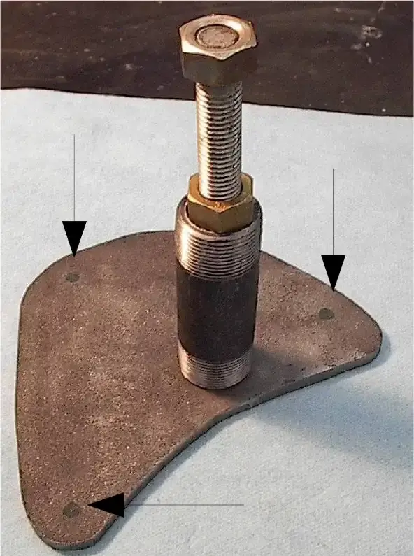
KTM Crank Removal & Case Splitter Tool
Getting ready to drill, weld and plate a KTM crank pusher.
A plate 1/4" thick was plasma cut to fit the engine case and curved to fit around the clutch basket. The bolt is 6" long and a 1" OD nut is welded to the top of the pipe nipple. The pipe nipple is 3/4 ID and cut 1 3/4" long (service 80 black pipe available from plumbing supply). The hole in the plate is 7/8" diameter. Weld the nipple to the plate, weld the nut to the nipple and thread the bolt in it.
To split the cases, bolt the tool to the cases via 3 each 6mm screws. Thread the bolt down to the left end of the crank, make sure all the Allen screws are removed from the right cases and tighten the bolt easily until the cases split. open the cases and then finish turning the bolt until it pushes the crank out.
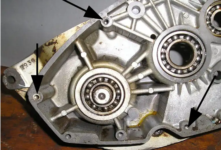
The tool is designed to fit over the end of the crank and bolt to the holes shown by the arrows. Plate is curved to fit around the clutch basket without the clutch being removed.
KTM Clutch Nut Tool
A flat blade screw driver is what Kip uses to hold the end of the screws and a hollow tube 10mm socket to turn the nuts.
HOME MADE SACHS TOOLS
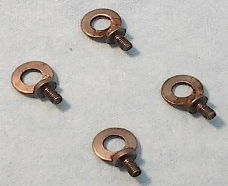
6mm Thumb Screws
These were designed by Ted/ Dane Leimbach for use on Sachs holding plates to make it fast and easy to secure the plates to the engine cases.
8mm flat washers are brazed to the heads of 6mm screws.
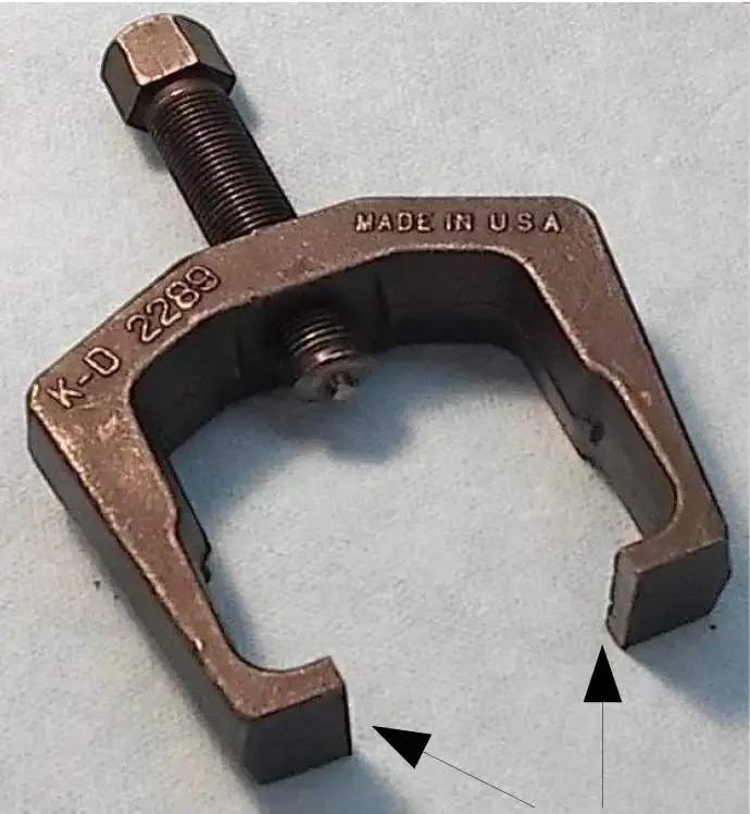
Sachs Counter Shaft Sprocket Puller
This is a modified pitman arm tool (K-D #2289 which is available from automotive stores). The bottom fingers were shortened (shown by arrows) to allow it to fit under the sprocket.
CAUTION: use a 13mm socket over the end of the Sachs mainshaft for use as a protective cap before using any puller. Failure to do so will cause the end of the mainshaft to break.
by Alan Buehner
Originally printed in the 2010 issue #49 of Still….Keeping Track
Working on Sachs and KTM engines can be intimidating even for a seasoned mechanic who has never worked on these engines before. When you go through the repair manuals, there is a page showing a drawing of all the special repair tools that you are led to believe that you are required to have in order to pull the engines apart and re-assemble them. These tools help to help make the job easier and enable you to do the job properly. Most of these tools are unobtainium (Latin for not available) but some of these unobtainium tools can be easily made and are already in your tool box. This article is to show you how.
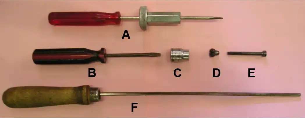
Ignition Advance Timing Gauge
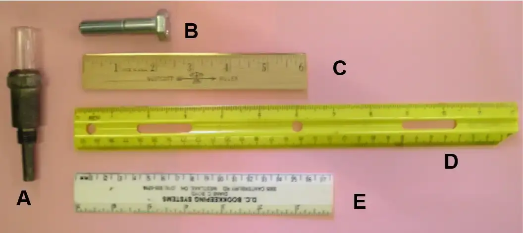
This is a photo of a factory ignition timing gauge (item A) and a sample of what you need to make your own. Item “B” is a 10MM hex head bolt that is at least 2 inches long. Items “C,D, & E” are samples of inexpensive metric rulers that can be bought or may be laying around in a desk drawer at home or in your office.
The factory ignition timing gauge (item A) is a spring loaded plunger device with a clear glass window on the top. You screw it into the spark plug hole and as you bring the piston to top dead center, the piston pushes the plunger up and the top part of the plunger rod shows up in the window with grooved lines on it, spaced 1mm apart. When the piston reaches top dead center, you back it down and start counting the grooved rings for the timing. When you arrive at the timing you need, you run your pin through the Motoplat flywheel to see if it is correct.
The bolt (item B) needs to be 10 or 12mm in diameter so that it will fit into the spark plug hole on the cylinder head and yet is big enough so that it will not fall down inside. It must be long enough to rest on top of the piston at top dead center and be long enough to ride the top of piston down without hanging up on the cylinder.
The sample rulers shown are all too long to be used when timing an engine that is in the frame and must be cut short enough to fit the tight space between the cylinder head and frame.
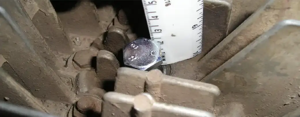
This photo shows how to use the bolt and ruler on a KTM cylinder. Hold the ruler next to the bolt (at T.D.C.) then slowly turn the flywheel counter-clockwise as you watch and count the bolt drop down along the ruler to the required number of millimeters for the timing.
Spanner for Sprocket & Flywheel
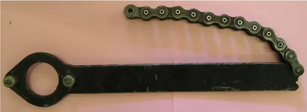
Photo of a factory made spanner. This tool was designed to work on the Sachs and KTM engines. The chain wraps around the sprocket and the extra chain is held in your hand against the metal bar. The end of the bar gets jammed against the teeth of the sprocket to hold it immobile while you remove or tighten the sprocket nut.
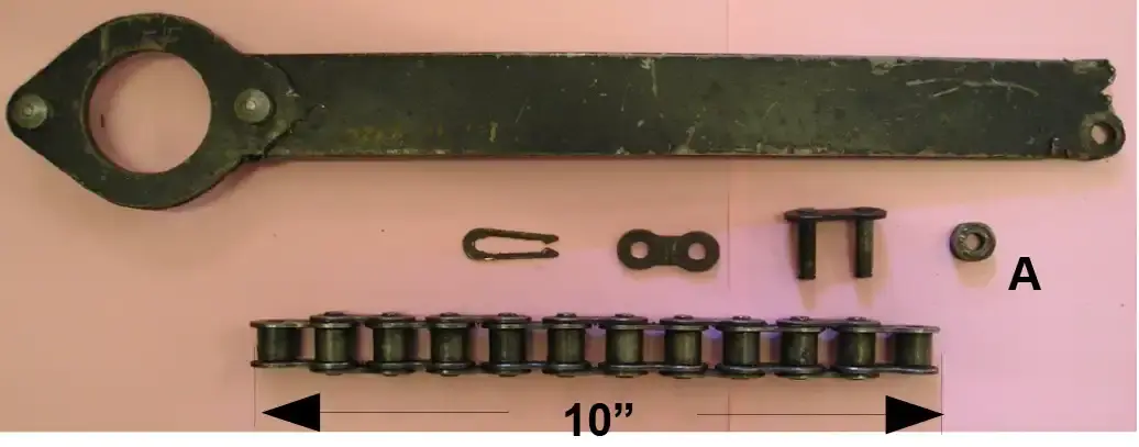
This is a photo of the factory spanner with the chain removed. As you can see, this tool is very simple to make. All you need is a bar of steel 1-1/4” wide x 1/8” thick x 10” long. The chain is 10” long and can be made from any scrap from that you have laying around (new or used). NOTE: a spacer bushing (item A) is used on the steel bar when inserting the master link to help support the chain and prevent the bar from wiggling around when using it.
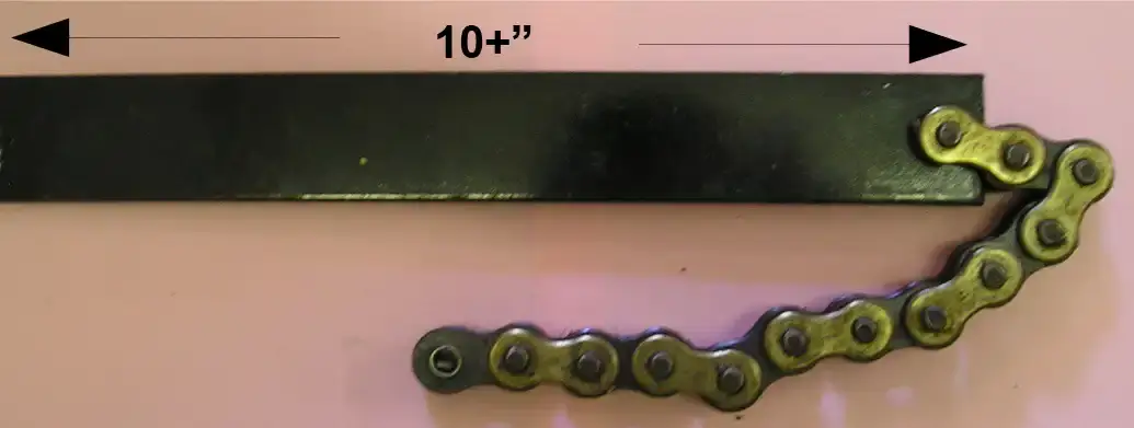
This photo shows a sample of a home made spanner. The mounting hole is shown in the center but can be also be near the corner of the bar (as shown on the factory spanner). You can make a separate spanner with a 428, 520, and 530 chain or just remove and replace the chains when you need to. The master links make changing the chains fast and easy.
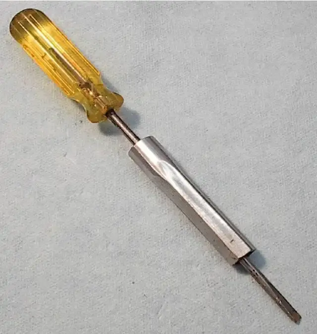
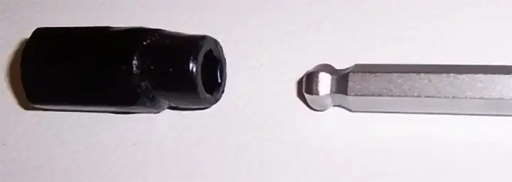
KTM Screwdriver for Clutch Screws
Item “A” shows a factory screwdriver for removing and installing KTM clutch nuts (D) from screws (E). Item “B” is an ordinary flat blade screwdriver that will fit into the slot of screw (E). Item “C” is a 10mm socket found in your tool box that will fit over the nut (D) and is used to remove or install the nut while the screwdriver (B) is inserted through the 10mm socket and is used to keep the screw from turning.
The special KTM hex screw driver (F) is only used if the slot end of the screw is broken. It is rarely needed or used.
by Alan Buehner
Originally printed in the 2010 issue #48 of Still….Keeping Track
The bikes are pretty much standard Penton 125 six day models from 71 or 72, however, I got permission from our governing body to fit the later model type 51 engines after the Sachs gearbox locked up throwing me down onto the road.
Basically, engines are stock, with a little porting like widening the exhaust and generally just cleaning up the inlet and they run 36mm Bing’s on them and run on methanol. Frame is standard six day frame, just with excess brackets cut off.
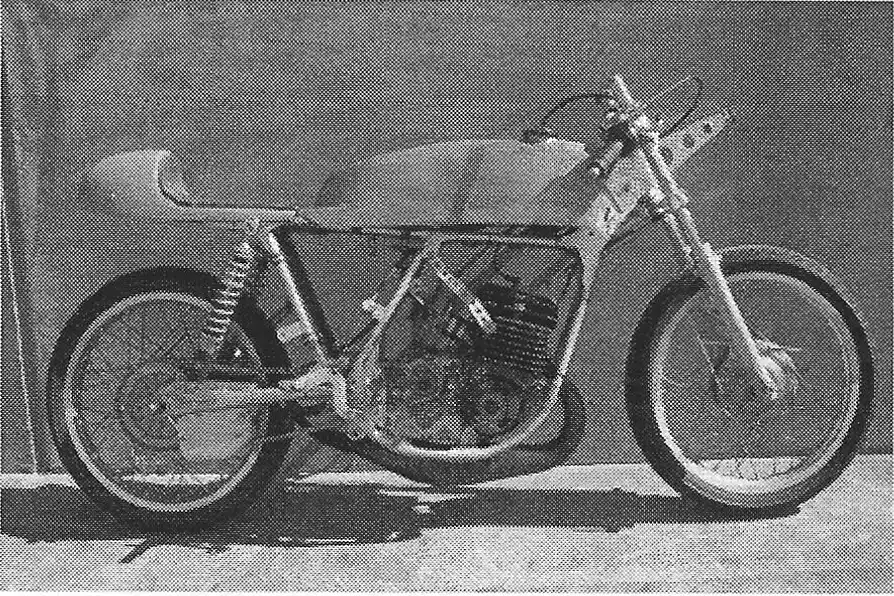
I have sent you pics before, but maybe back then my 125 was green and silver. You can see the pic of the 72 frame which shows where our friend Steve Ling, cut the frame after I got it on e bay, and I welded it back together.
One of the other pictures shows like a cotton reel thing I had to make so I could get some reasonable gearing past the clutch mechanism.
Only thing I want next is some good front brakes, maybe some twin leading shoe front ends from some old CB Hondas, as they have to be pre 1972.
As mentioned previously, Bert Flood Imports (who I have worked for for the last 30 years or so) used to be the Australian KTM importer for 22 years up till 1994 and I do know a thing or two about the KTM. We are still the distributor for Rotax.
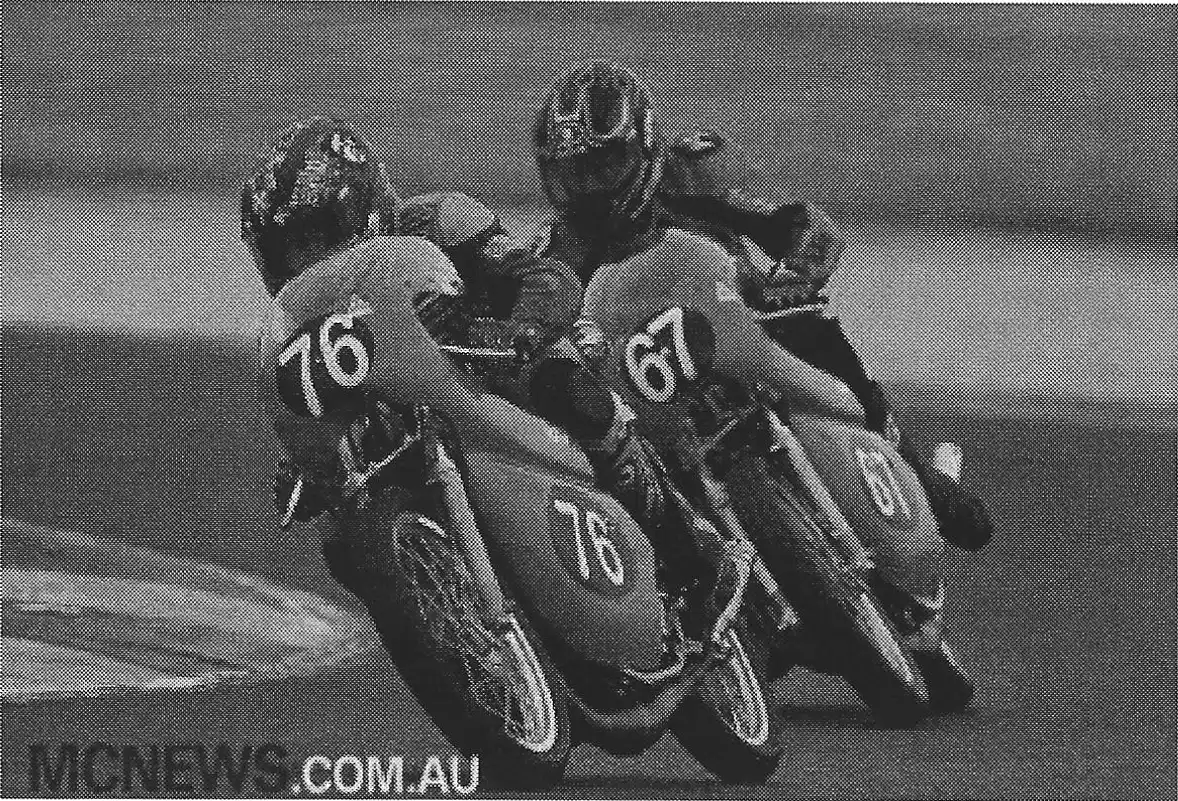
And I have a lot of correspondence with my contact in the motorcycle division. The pipes on the 125’s are actually off one of their roadracer and work very well and the pipe on the 350 has the same dimensions as a TSS 350 Bultaco roadracer pipe. My boss here still campaigns a couple of them in the 350 class (ridden by Ginger Molloy from New Zealand , who was runner up in the world championship in 1969 to Agostini).
I would be interested to know what ignition curve the PVL ignitions have. The Motoplat works reasonable, however I am always looking at anything that may be better. The Motoplat I am using is not a standard KTM one, its actually off the Rotax 256 roadracer engine.
The only other thing that would be nice would be a close ratio gearbox instead of the standard wide ratio I have, but unfortunately I can not afford the money to have one built.
Mark Lester
Australia
Photos and story provided by Mark Lester
by Doug Bridges
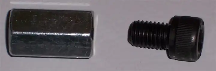
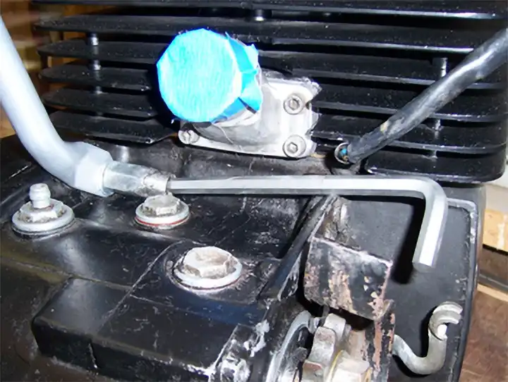
I recently came up with a solution to the problem of tightening the nut that fastens the left side frame brace to the engine on the early 175 KTM motors. Someone may have already come up with this, but just in case I am sharing my solution.
I took a 10mm coupling nut and screwed a 10mm x 5/8 Allen head bolt in the end and then welded it to the coupling nut. Then using a special Allen head wrench that allows you to tighten it from an angle ( bought the sets at Shucks Auto parts) I am able to tighten the nut even with the cylinder and carb mounted.
What's the difference?
by Alan Buehner
Originally printed in the 2010 issue #46 of Still….Keeping Track
The purpose of this article is make you aware that there were several different sizes and styles of spacer tubes used in the front hubs of the Penton and KTM motorcycles. Their purpose is to secure the inside part of the wheel bearings, space the bearings inside the hub so that the wheel, when mounted on the forks will be centered, and to allow the front axle to be easily removed or installed.
The most obvious difference is that some are threaded on both ends, and some are threaded on one end. The double threaded tubes were used on the early Penton motorcycles – from 1968 thru 1973. The single threaded tubes were used on all Penton and KTM bikes from 1974 thru 1978. From 1979 onward, the threads on the tubes were eliminated. Fine thread nuts were threaded onto the tubes to secure spacer bushings as shown in drawings 1 and 2.
Threads on the tubes caused a couple of problems. The first problem was trying to remove the brake backing plate so you could service the brake shoes. On the 1968 thru 73 bikes there was a nut securing the backing plate to the spacer tube and this nut had to be removed.
Anyone who has performed this “task” knows that 90% of the time that you try and remove this nut, it is the nut on the other side of the tube that loosens and turns, not the nut for the backing plate. The reason being is that you have to put a wrench or socket on both nuts to prevent the spacer tube from turning, which is why KTM switched over to the single threaded tube (see photo C). The backing plate can be removed without removing a nut and a hole was drilled through the tube to allow you to insert a screwdriver or rod to keep the tube from turning when you needed to remove the nut on the left side of the hub.
The other problem with threaded tubes is the risk of damaging the threads. If the threaded end is not protected when trying to remove the bearings, the end(s) can mush-room, thus damaging the threads and you will not be able to thread the nuts back on. Another problem is trying to hold the tube secure, after removing the backing plate, so that you can remove the nut on the left side of the hub. Not taking precautions can cause the outside edge of the threads to become flattened and you will not be able to thread the nut back on.
If you don't know better, the tubes look the same and should be interchangeable. But by looking at the dimensions on the photo, you can see that the centers (spacer for the bearings) are the same but the overall length of the tube and the left and right ends are different which will cause problems in trying to center a wheel in the front forks.
Tube “A” is part number 51-09-011-000 which is used in the narrow type ES 1-579 32mm Ceriani forks. It did not provide enough spacing to allow the installation of a speedo drive unit. This is an oddball part used on only a few bikes.
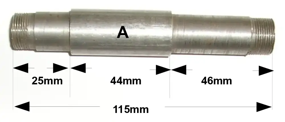
Tube “B” is part number 52-09-011-000 which is used on most 1972-73 125 & 175 bikes. It requires either a speedo drive unit or a spacer bushing (item #28 Drawing 2).
Tube “C” is part number 51-09-011-300 which is used on all Penton & KTM bikes from 1973+ using Ceriani and Marzocchi 35mm forks. This tube also It requires either a speedo drive unit or a spacer bushing (item #28 Drawing 2).
So when in doubt, measure your existing spacer tube before looking for a replacement and always try and obtain a “C” style tube.
What's the Difference?
by Alan Buehner
Originally printed in the 2009 issue #45 of Still….Keeping Track
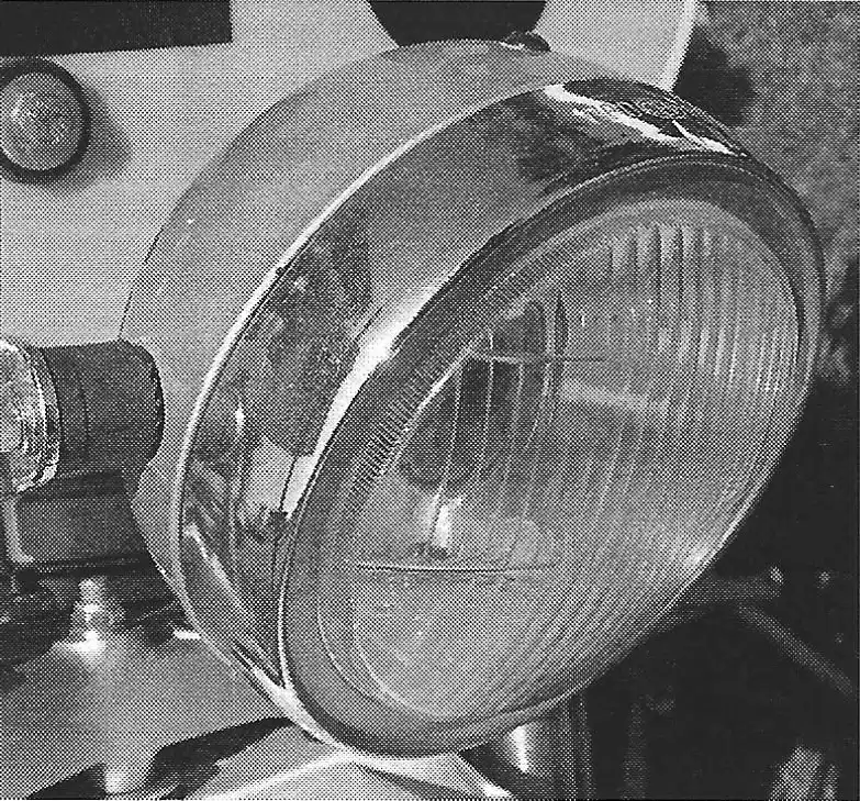
Penton motorcycles were equipped with a variety of styles of head lights to convert the bikes from MX to Enduro models. The head lights being featured in this article are the most popular ones to be found but are not the only ones to be used.
A. The small bullet head light (part no. 7-1-000) is easily identified because of it's “bullet” shape and the “pull-out” exterior switch mounted on the back. It has a 3-1/2” diameter one piece glass reflector (part no. 7-6-000) and uses a 6v 15-15watt bulb (part no. 7-8-000) that twists into a socket that is attached to the back of the reflector. This head light bolts directly to the fork mounted brackets using 2 rubber bushings as spacers (as shown in photo).. This head light was commonly used on any of the 1968-71 steel tanker bikes up to the 1972 CMF bikes.
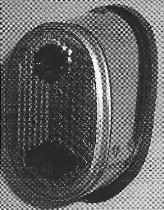
B. The large CEV head light has 2 identifiable features, the red high beam indicator on the top and the rounded front glass reflector. It uses a 6v 35/35watt bulb (part no. 31-11-038-000) that twists into a socket attached to the back of the reflector. The glass front is a separate part from the chromed metal reflector. This head light bolts directly to the fork mounted brackets. This head light was commonly used on the 1971 steel tanker bikes up to the 1972 model bikes.
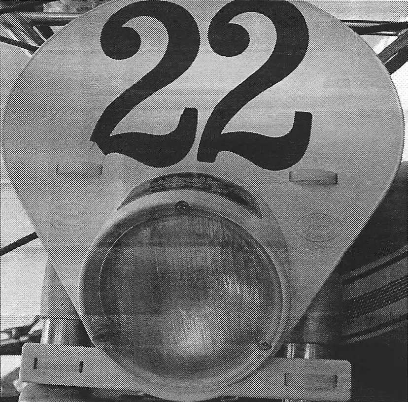
C. The large ZKW head light has 2 identifiable features, the blue high beam indicator on the top and the “flat” front glass reflector. These are also commonly found with a number plate bracket bolted on the top. It uses a 6v sealed beam bulb (part no. 51-11-030-300) with 3 prongs on the back that “plugs” into a wiring socket. The head light bolts directly to the fork mounted brackets. This head light was commonly used on the 1973 to 1975 CMF bikes.
D. The Preston Petty head light – number plate became the the universal head light of choice for use on dirt bikes. They came in many different colors and were easy to mount on any type/ brand of motorcycle. They used a 6v GE Tractor bulb which were available from Auto Parts stores and Farm Suppliers, and could be used on 6v or 12v electrical systems. The original head lights were mounted using 4 plastic brackets that bolted to the front forks and were screwed to the number plate. These were later revised with slots in the number plate and used 4 zip ties to easily fasten the head light to the front forks (as shown in photo). These head lights were very durable, almost indestructible and were used to replace existing head lights when they were damaged from crashes.
The Preston Petty head lights were carried in the High Point Accessories catalog and were sold through motorcycle dealers throughout the country. The Petty Headlight and fender with built in tail light revolutionized the enduro market. It eliminated the need for individual units that were difficult to mount and wire. Penton motorcycle dealers no longer needed to order the “lighting kits” for their customers which were becoming expensive and could easily set-up a bike for enduro riding by pulling a Petty head light from their inventory.
What's the Difference
by Alan Buehner
Originally printed in the 2009 issue #44 of Still….Keeping Track
During the brief 10 year period of the Penton motorcycles, there were a variety of tail lights that were used on the bikes. Up until 1976, all of these bikes were basically motocross bikes and a lighting kit was added to make them “Enduro” bikes. Tail lights were obtained by KTM from different manufacturers in Europe (mainly from CEV in Italy) and the styles changed in order to cut costs and provide durability to suite the punishment they were to be given with off-road riding.
The steel-tank Penton motorcycles were equipped with the large size CEV tail lights as shown in photo “A”. The part number for this light is #5-56-000, and is shown in the “Spare Parts Manual – 002 and 003. These were mounted on a long steel bracket which was then bolted to the alloy rear fenders. This particular light was commonly used on a variety of European street bikes. Although the light, being large in size allowed for good visibility, it, like the alloy fenders was prone to breakage in crashes. Although this part is shown in the 1972 parts book for the CMF Pentons, I have never seen them on those bikes. This light used 1 double filament 6v 5/18w bulb (part #52-11-045-000).
There was small tail light, as shown in photo “B” that was used on the early bikes with the alloy fenders. This light (part #7-16-000) had a slight curve on the bottom and it bolted directly to the fender with 2 studs and nuts. It used 2 small 6v 4.5 watt screw-in bulbs.
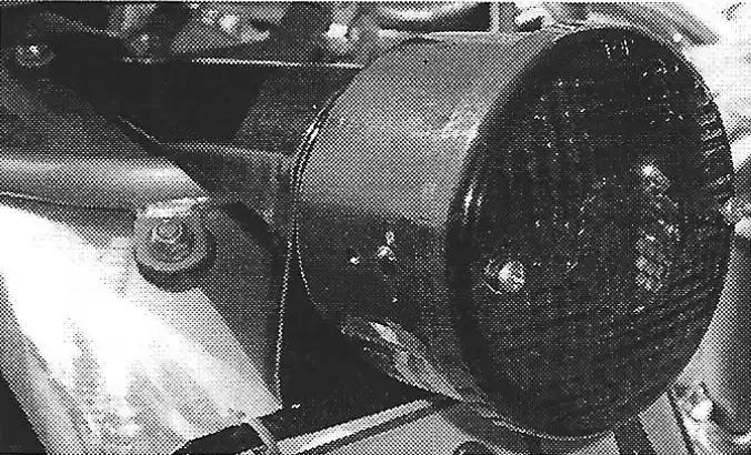
A common tail light was the small, metal, rectangular style shown in photo “C”. The part number for this light is #51-11-040-300. These were first mounted on a steel plate that was mounted to the alloy rear fender with rubber bushings. With the use of plastic rear fenders, the steel plate was replaced with a rubber flap that was bolted directly to the fender. This light used 1 small, tube style 6v 3 watt bulb (part #51-11-045-000).
Although this was not a factory supplied part, the rectangular light shown in photo “D” was a part used on semi-trailers and was a good substitute for the small metal tail lights. They bolted to the rubber license plate flaps and were very durable. They used a single 6v bulb.
In 1973 the medium sized CEV tail lights, as shown in photo “E” were provided by KTM to meet federal regulations requiring better visibility from tail lights. This design was the most popular used on the Penton motorcycles from 1973 through 1975 (part #51-11-040-300). These were mounted on rubber license plate flaps which were then bolted to the rear fenders. When Hi-Point came out with their “enduro” style plastic fender, these lights bolted directly to the “hump” on the fender (as shown in photo “E”. This light used 1 double filament 6v 5/18w bulb (part #52-11-045-000).
Finally, in 1974, Preston Petty extended their line of plastic rear fenders to include one with a built in Tail light, as shown in photo “F”. These were very popular and were an easy way to convert your Penton bike to an enduro set-up. The flat spot on the back part of the fender also provided a convenient place to mount your license plate. These fenders were also used as replacements when your stock plastic fender broke. These fenders were featured in the Spring 1975 Hi-Point accessories catalog.
by Alan Buehner
Originally printed in the 2009 issue #43 of Still….Keeping Track
The steering races need to be checked on a regular basis to make sure that they are kept greased and are not worn or loose. This is a maintenance item that is often overlooked. The best time to do this is when replacing the oil in the fork tubes.
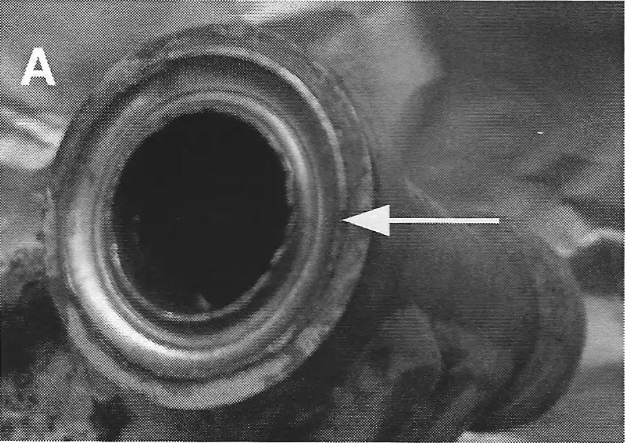
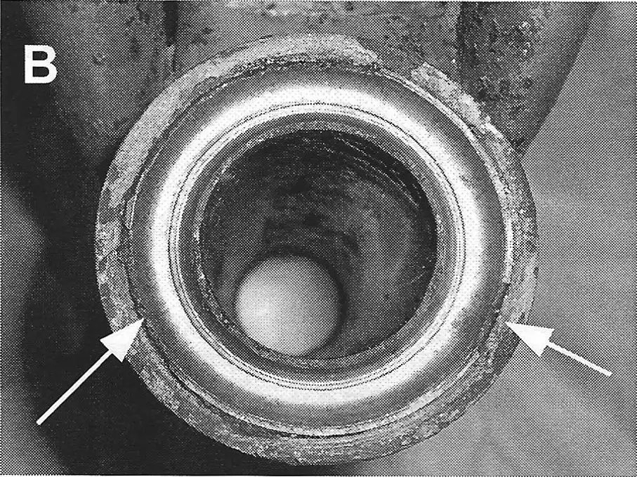
A close visual examination of the races will determine if they need to be replaced or reused. The top two photos show the inner races inside the top and bottom of a steering head. Notice how the inside and outside edges of the races are broken and have wear marks. These are signs of a race that needs to be replaced. When in doubt – replace it.
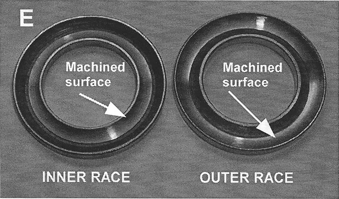
There are two types of races used on the Penton Sportscycles – an inner race and an outer race.
The inner race has a machined surface (that the balls ride on) that is on the inside track of the race (see photo E). This race is used in the top and bottom cups of the steering head.
The outside race has a machined surface (that the balls ride on) that is on the outside track of the race. This race is used in the cup at the bottom of the fork stem and in the cup of the threaded top bushing.
To remove the old races is simple. You just tap them out.
For the steering head, insert a long tool down inside the neck. Hold the tool against the inside edge of the race and tap the tool with a hammer and moving the tool around the edge of the race as you tap it to gradually loosen it out of the cup.
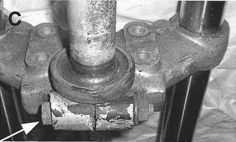
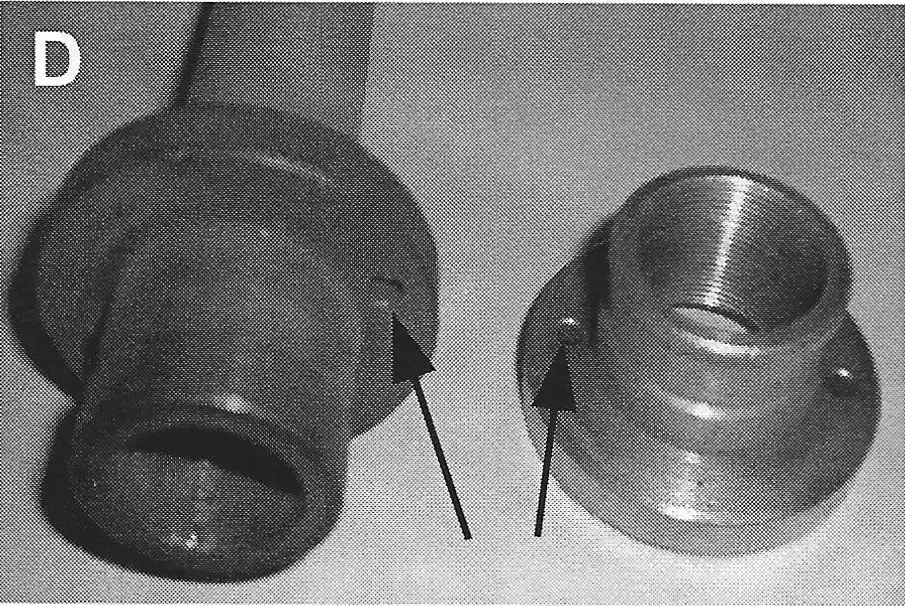
To remove the old race out of the steering stem, you must first remove the steering stem from the bottom fork plate. Remove the pinch bolt on the fork plate (see photo C), then tap the fork stem out. On the bottom of the fork stem cup are two small holes (see photo D) use a punch inside these holes to tap the race out of the cup.
On the threaded top bushing there are also 2 small holes (see photo D). Use a punch inside these holes to tap out the race.
To make removal and installation of races easier – heat the outside surfaces of the holding cups to make the metal expand.
Installation of the new races is a matter of pressing or tapping in the new races. Make sure that you are installing the proper race – inner races inside the steering head – outer races in the fork stem and top bushing.
Steering race kits are available that include: races + balls + o-rings. Use a Lithium based grease or steering race grease to lubricate the assembly.