

KTM Air Boxes
What's the Difference
by Alan Buehner
Originally printed in issue #62 of Still….Keeping Track
There have been a lot of changes and improvements to the air boxes used on the Penton/ KTM bikes from 1972-82. The purpose of this article is to point out and show through photos from the parts lists what the differences are and what the different components look like.
With the introduction of the CMF bikes in 1972, one of the big changes was the fiberglass air box. It was designed to hold a lot of air space and most importantly, be made water proof.
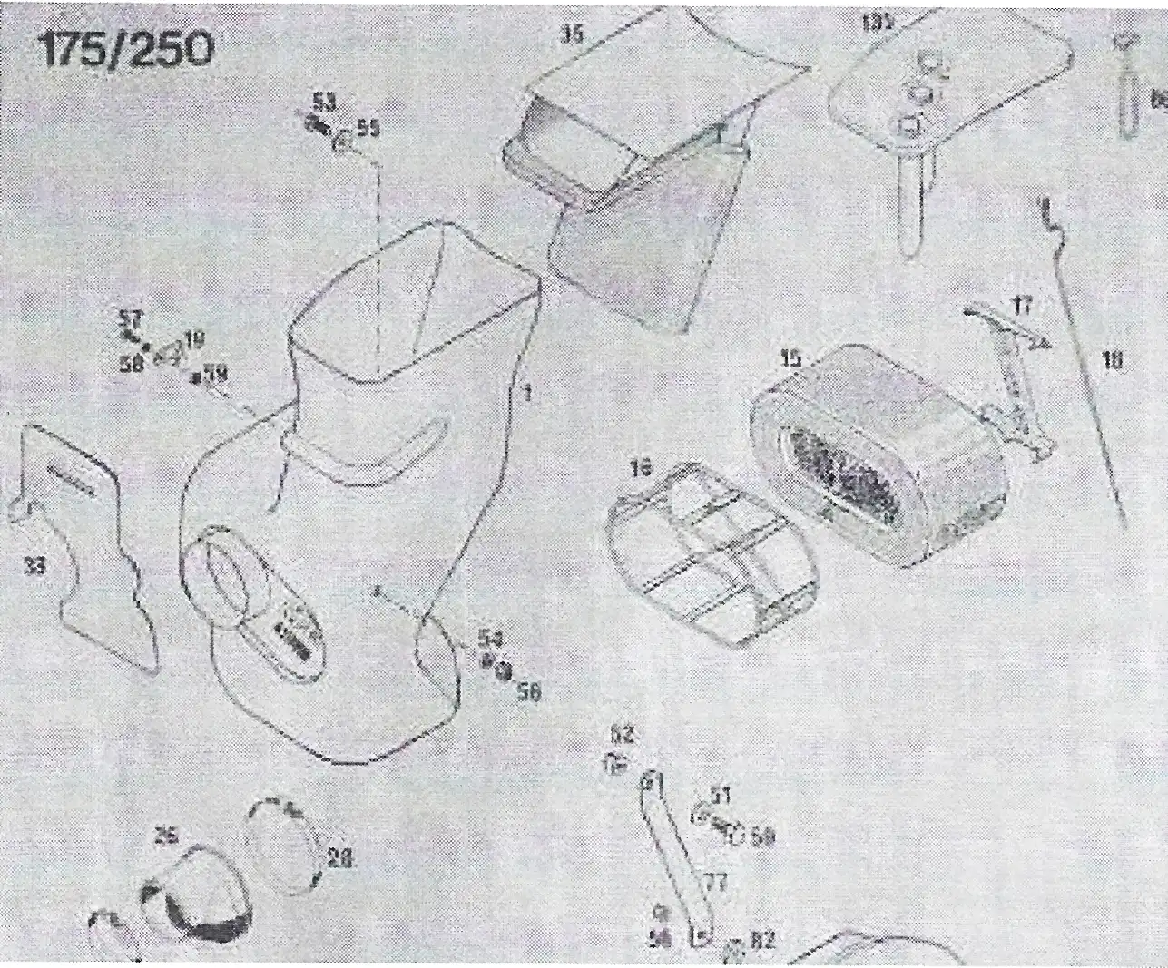
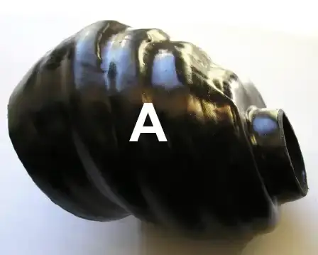
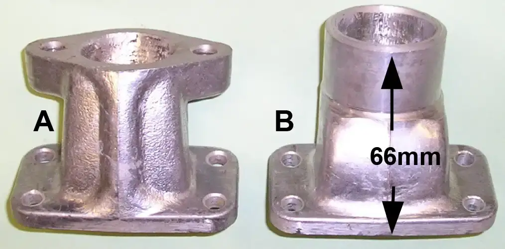
Photo “A” shows what the air box looked like for the 1973-73 bikes. The arrow points to the extension on the left that allowed the right side number plate to be bolted to it.
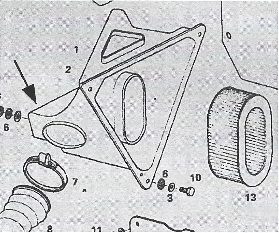
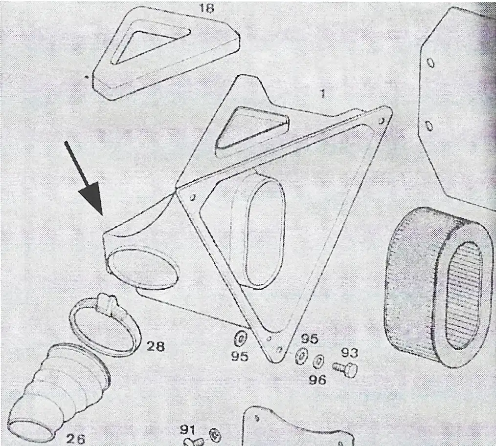
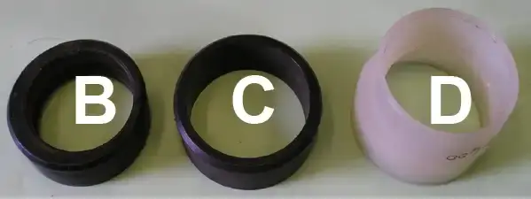
The arrow in photo “B” shows how the air box was modified, starting with the 1974-76 bikes. These bikes came with number plate/ heat shields and the extension was removed. The 1972-74 bikes all used the same air boot and air filters. The air filters shown are the paper filters that where replaced with the foam air filters which could withstand the infiltration of water into the air box.
In 1976 a new lighter weight frame was introduced for the MC-5 bikes as shown in Photo “C”. The air box for these was made of alloy and this air box was used on all the 1977 GS6 and MC5 bikes. It uses a round foam air filter that fits onto a round cage in order to mount it and help it keep it's shape. This new design created confusion because instead of just one air boot fitting all sizes of engines, there were six different styles and lengths of air boots that were created. Three of the air boots offered are shown in the photo.
To add to the confusion, there were different lengths and styles of intake manifolds for the Bing and Lectron carburetors used on all the engines. (see Tech Tips #54 – KTM intake manifolds and Tech Tips #55 – KTM air boots).
This alloy air box worked well for protecting the engines from dust and dirt but could cause problems in high water if the top and side of the air box were not properly sealed.
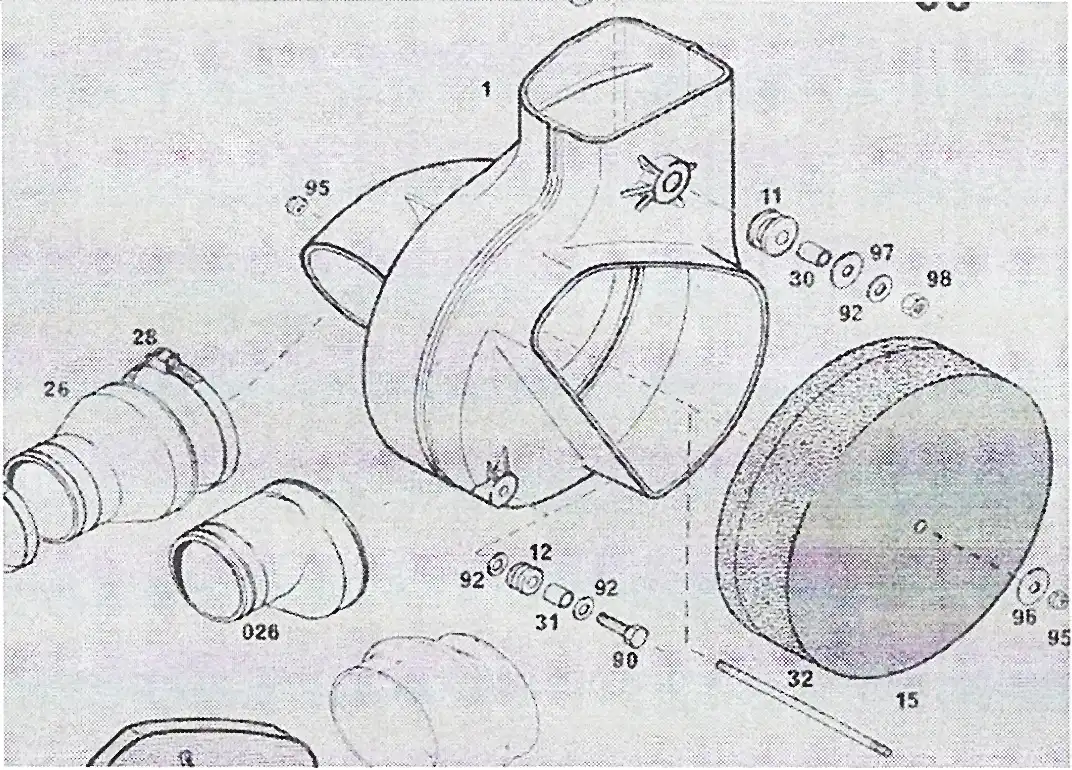
In 1978 KTM came out with a plastic air box for the MC5 bikes as shown in photo “D”. I assume that this was done to cut production cost. It was similar in design to the alloy air box with an opening on the side to allow changing of the air filter, and an opening on the top. This new design created more of the same problems, more new air boots, problems in sealing the openings against water coming in, and a new style air filter cage.
The good news was the foam air filter is the same as the one used on the 1972- 76 bikes. The bad news was that the cage has two stud that get pushed through two holes in the air box to secure it. Unless you have skinny hands this is a big challenge trying to get the cage assembly lined up with the holes. The other challenge was getting the nuts and washers on and off with the carburetor and air boot in the way. Needless to say, this air box was used only one year.
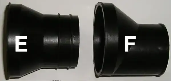
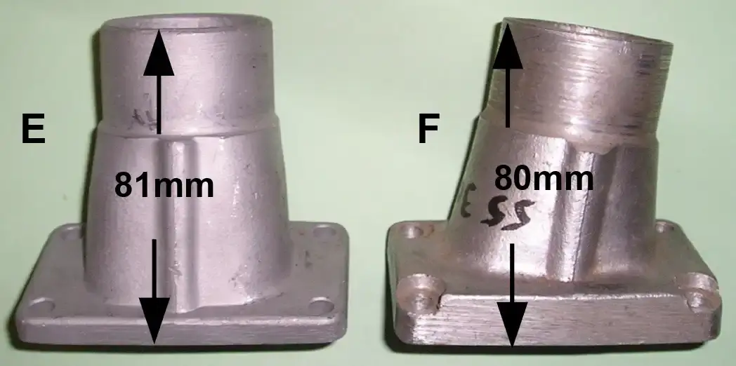
Photo "E" shows a new and improved plastic air box that was used on the 1979-81 bikes. It required different sizes of air boots but the oval air filter cage was a throw back to the 1972-76 bikes which was easy to change. It was inserted from the top of the air box and held in place with a rod and plastic filter support.
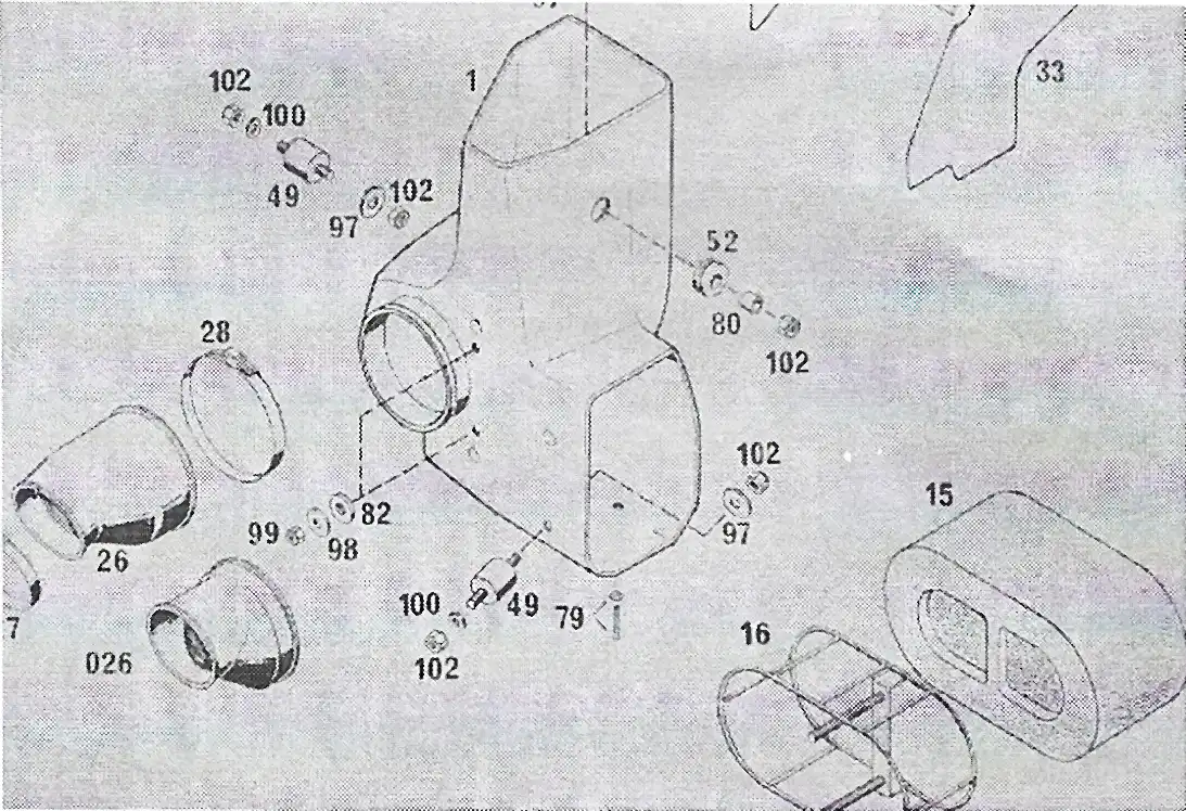
In 1980 a new frame was designed for the 125 and 420 bikes and they came with a new style plastic air box. This air box was mounted higher up into the frame and the air boot was attached to a round, hard, plastic base that mounted in the bottom of the air box (see photo "F").
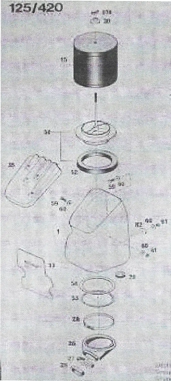
It used a new style canister style foam air filter that could be easily serviced from the top of the air box.
Apparently there were design problems with this air box since it was used only for one year.
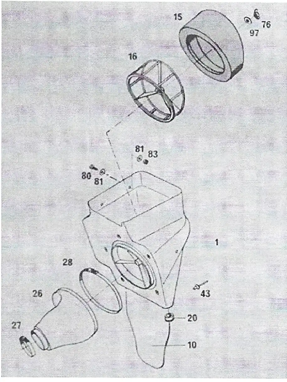
In 1982 the next generation of plastic air boxes was introduced on the 250 and 495 bikes (see photo "G"). It used a newly designed, round, air filter cage that required a newly design foam air filter to fit it. This assembly was held in place over a threaded rod inside the air box, and secured with a washer and wing nut. This air box used only one large air boot to fit both engines. It also had a stiff mud flap molded to the bottom of it.
What's the Difference
by Alan Buehner
This article is to show the what the different brake cams and arms look like that were used on the Penton and KTM bikes - from 1968 thru 1980.
Front Wheel Brake Arms
Rear Wheel Brake Arms
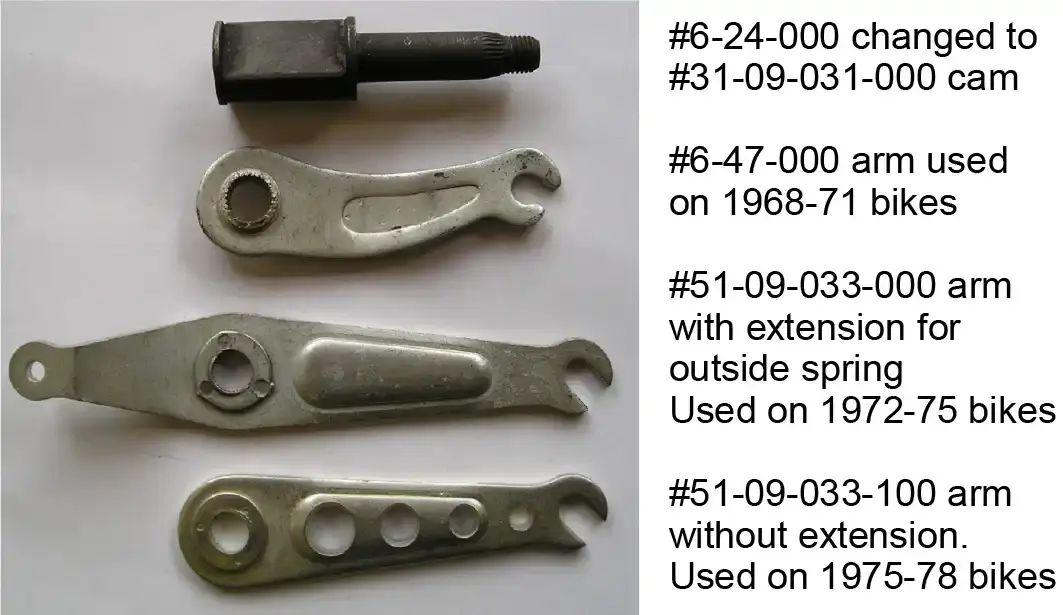
There were 2 different type of cams and 2 different groups of brake arms used on the Penton and KTM bikes from 1968-1980.
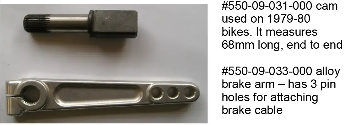
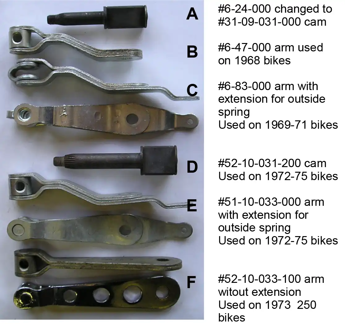
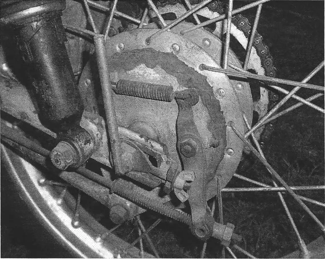
The first group, as shown in photo 3, utilized brake cams with a tapered spline and a threaded end. Parts “A thru C” were used on the 1968-71 Steel Tank Pentons. The 1968 bikes came with the short arm (item “B”) and these were switched over in 1969 to arms with an extension (item “C”) for an external spring. Item “C” shows a front and side view of what they look like.
The cam “D” was used on the 1972 thru 1975 100/ 125s, the 1972-73 175s that use the straight hubs with the cush drives and the 1973 250's with the conicle hub. The arm (item “E”) was used on the 1972 thru 1975 100's and 125s and the 1972-73 175s. A front and side view of this part is shown. It has the extension for the external spring and is bent to keep the brake rod from rubbing on the backing plate.
The arm (item “F”) was used on the 1973 250s. A front and side view of this part is shown. The arm was shortened, eliminating the use of the external spring, and the arm is straight.
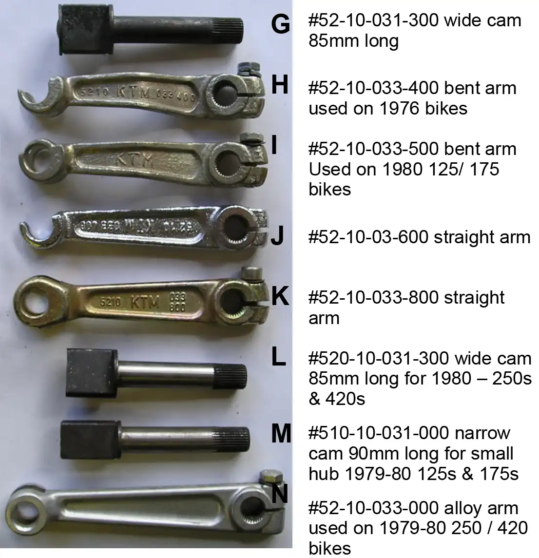
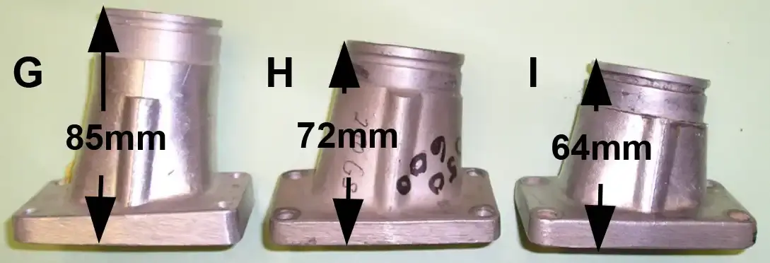
The items show in photo 4 show the different brake cams and arms used on the bikes with backing plates for the 1976+ conicle rear hubs. The cams had straight splines that required new style arms with pinch bolts. Now this is where the confusion comes in. Items H to J have the same casting with the same part number (52-10-033-400) but are different as shown. Item H & I are bent and item J is straight. The casting has a closed loop for the brake rod saddle and the top part of this loop was machined off on some of these (as shown on H & J) to allow quick removal of the brake rod.
by Alan Buehner
This article is to show the modifications that George Bliss made to his 1970 Penton 125 after he purchased it, to make it enduro ready. These mods were made from his years of experience in riding the Jack Pine Enduro in Michigan from 1951 thru 1969 and his friendship with John Penton who shared his recommendations.
by Alan Buehner
The Sachs Clutch assemblies are very dependable and almost never wear out. However, there are some problems that are now showing up after 40+ years.
One of the most common problems you can expect if the engine has been sitting for a long time of nonuse is stuck clutch plates. The plates can be broken loose if they were sitting for only a few weeks of nonuse by starting the engine up in neutral, pulling the clutch lever in and putting it into 1st gear. After a couple attempts of the engine stalling out they should break loose and you will be good to go.
If the engine was sitting unused for years, the steel and fiber plates will be bonded together and the only way to loosen them up is to disassemble the clutch and pry the plates apart.
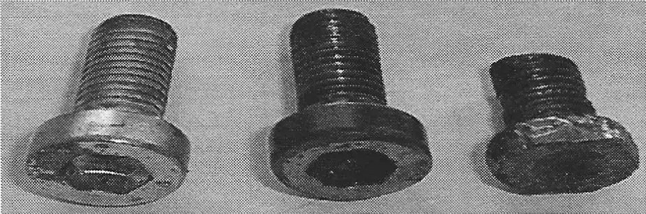
The Sachs clutch assemblies are very easy to remove from the engine. All you have to do is remove the pressure plate and then the snap ring. It can get difficult to disassemble the clutch if the Allen screw heads were worn down (see photo A). The locking nuts have to be removed first. The screws were coated with a locktite TM material and if you cannot get an Allen wrench to grip into the screw head you will have to use a pair of dykes to bite into the sides of the head to tum them. I would recommend using a dremmel tool with a cutting wheel to cut off the exposed bottom of the screw (as was done to the screw on the right). If the heads of the screws are worn, replace them with new screws - part #2740-024-002.
Once the screws have been removed you can remove the basket, the springs, and the clutch plate stack. Using a small regular screw driver, carefully pry all the plates apart. The facings on the plates will most likely all be rusty. The fiber plates can be cleaned up with steel wool. These plates are almost indestructible and only need to be replaced if chuncks of the corking came out of them when prying the plates apart.
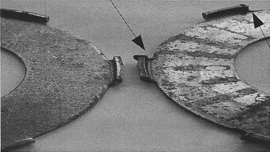
The steel plates can also be cleaned up with steel wool, but take a close look at the little tabs that stick out of the clutch basket. If they are smashed up ( as shown in photo B), then they should be replaced with part #0259-109- 000.
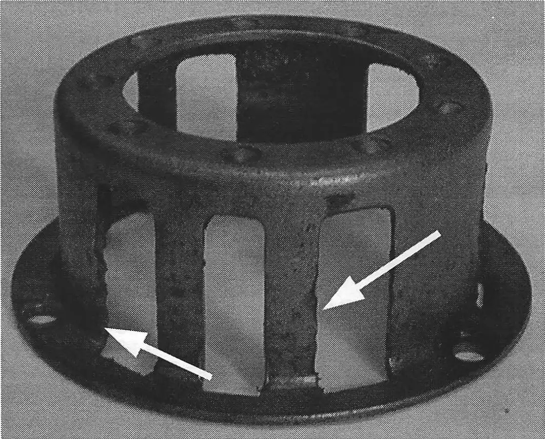
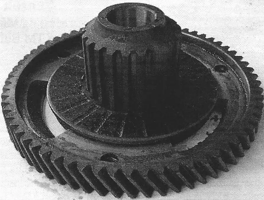
Take a close look at the clutch basket (photo C). There should be some wear, called saw toothing, where the tabs on the steel plates hit the sides. These edges can be filed down to prevent the plates from getting hung up. If the saw toothing is severe, you will need to replace the basket. Filing down the edges will create a gap and will cause more saw toothing, allowing the tabs on the steel plates more movement to bang against the basket, and wear faster, especially if the bike is ridden very hard.
NOTE: there are 2 sizes of baskets. Part #0658-002- 000 measures 40mm high and was used on all the SA engines. This basket uses springs that measure 21mm long-part #0239-015-000. The 6 speed engines came with an improved basket that measures 41.5mm high Part #0658-002-100. This higher basket requires a longer spring that is 22.3mm in length-part #0639-106-000.
The pressure plate (photo D) is another item to be looked at. Check the edges of the fingers that insert into the layshaft wheel. File off any build up on the inside and outside surfaces.
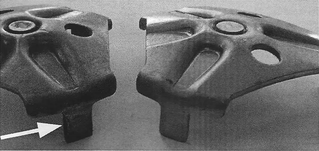
Check the center grommet for excessive wear. If the adjusting screw on the cam cup is set so that it is touching or applying pressure to the grommet, it will cause wear to the grommet. If the grommet is worn out, then the pressure plate will need to be replaced with part #0684-002-000.
These pressure plates are becoming scarce with only a few NOS ones available. Used ones can be used if they are not worn out.
Before attempting to reassemble the clutch plates to the layshaft wheel, take a close look at the bushing (photo E) in the center. See if it has any visible wear. Put the wheel onto the layshaft and see if there is any sloppy movement of the wheel. It should be a fairly snug fit. If not, replace the center bushing with a new one - part #0632-113-100. It is a press fit which means that you will need to heat up the layshaft wheel before pressing out the old bushing and when pressing in the new bushing.
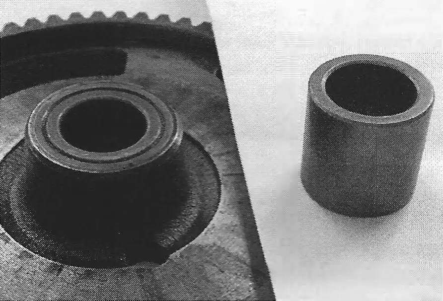
NOTE: many of the early layshaft wheel came with steel bushings. These were replaced with the brass bushing.
When installing the clutch plates, you must use a special tool (photo F) to line them up otherwise you will not be able to slide the clutch assembly back onto the layshaft. The special tool for this is the clutch hub - part #0658-001-000. Place the clutch hub tool on the layshaft wheel (as shown in photo E ) and then start stacking up the plates (a fiber plate goes on first), the springs, and the basket. After tightening up the screws and installing the locking nuts, you can then remove the tool.
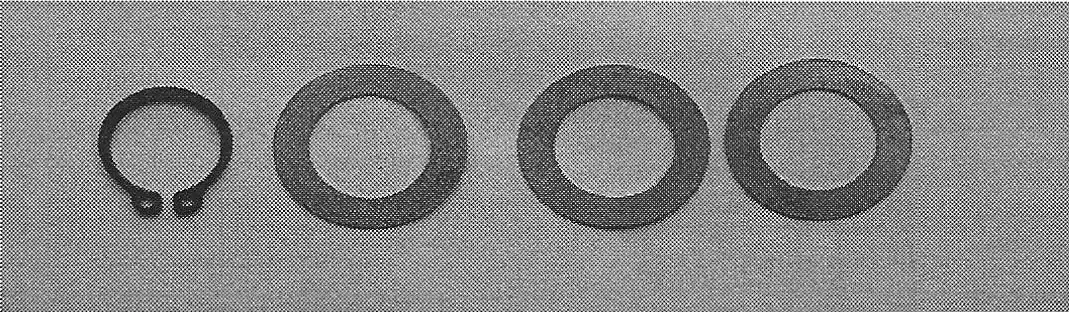
When reinstalling the clutch assembly on the engine, make sure that you install a shim washer before installing the snap ring (see photo G). There are 4 thicknesses of this washer - part #0246-015-000 is 0.3mm; 0246-015-001 is 0.5mm; #0246-015-002 is 1.0mm; and #0246-015-003 is 0.15mm. Use the proper shim to give an axial play of 0.0039 in (0.1mm) between the clutch layshaft wheel and the snap ring. If the snap ring is worn thin or has a loose fit, replace it with part #0245-020-005.
Install the pressure plate onto the layshaft wheel. Install the clutch case cover after applying a thin film of grease to the mating surfaces of the gasket and cases. If you are installing a new gasket, soak it in warm water to loosen it up. The wet gasket will also stick better to the grease coated cases and stay in place when inserting and tightening up the case screws.
After the clutch case is installed, turn the adjusting screw in the cam cup so that the screw is barely touching the pressure plate.
NOTE: this screw will cause excess wear to the center bushing of the pressure plate if it is applying too much constant pressure to it.
What's the Difference
by Alan Buehner
In the last Tech Tips article (#57) I showed the difference between the different Sachs cyliders. In this article my intention is to show the difference between the different cylinder heads used on the Sachs cylinders.
The first thing to know is there are cast iron cylinders and aluminum cylinders and there are different heads that go with these.
CAST IRON CYLINDER HEADS
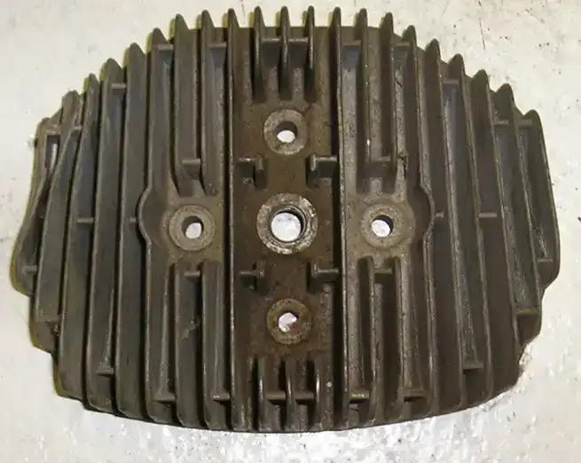
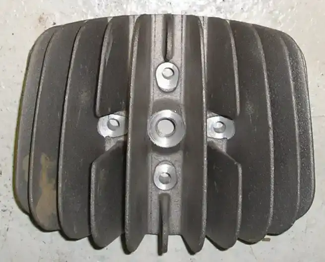
The cast iron cylinders came stock with aluminum heads as shown in photo “A”. They have short “butch” style short fins that were straight up and down These were used on the 1968 thru 1971 Sachs engines.
The cylinder head shown is photo “B” is the head off of a Puch cylinder. These were discoved by the racers to fit the Sachs cylinders and gave the engines a little bit more horsepower. These heads have short radial sunburst fins.
Both of these heads came in 2 sizes, one for the 100cc and another for the 125cc cylinders. The heads are dished out to accommodate the piston domes and allow for the proper “squish” area of the fuel air mixture. The 100cc heads have a smaller dome area measuring 50mm o.d. The 125cc heads have a dome area measuring 55mm o.d. These heads do not use any head gaskets. They simply just bolt onto the cast iron cylinder with 4 hex head bolts and washers.
ALUMINUM CYLINDER HEADS
The aluminum cylinders heads came in 2 styles and are available as 100cc or 125cc. It is important to know the differences between these for the bike application they will be used on. The heads are dished out to accommodate the piston domes and allow for the proper “squish” area of the fuel air mixture. The 100cc heads have a dome area measuring 50mm o.d. The 125cc heads have a larger dome area measuring 55mm o.d.
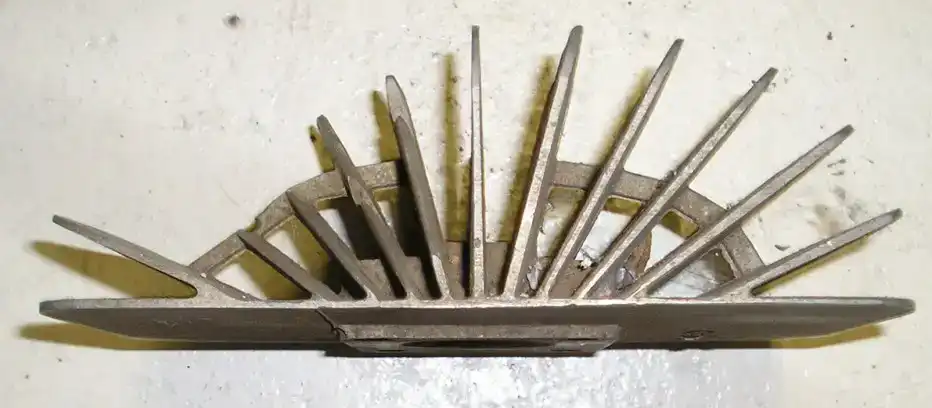
Photo “C” shows an alloy cylinder heads with the top 4 fins “cut off” on an angle (shown on the left side in the photo). These are used on Sachs engines using an up and over pipe. These are what are required on the Penton 1972 thru 75 CMF bikes where the exhaust pipe goes up and over the cylinder head. This allow a closer fit of the pipe to the head to allow the pipe to clear the frame.
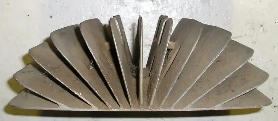
Photo “D” shows an alloy cylinder head with “full” radial fins. These are used on Sachs engines that use a side mount exhaust pipe. These are what are required on the Penton “steel tank” bikes that have the exhaust pipe mounted on the right side of the frame.
The aluminum cylinders require the use of a head gasket when installing the head. They are fastened together with 4 special long reach Allen Head nuts and washers.
The 100cc head gasket part number is 0650-113-000.
The 125cc head gasket part number is 0650-114-000.
What's the Difference
by Alan Buehner
From time to time I will get calls from someone inquiring about the availability of a cylinder for their Sachs engine. As far as they are concerned it is just a matter of letting me know that it needs to be for a 100 or 125. There reality is that there are several types of cylinders for the Sachs engine and it helps to know the difference to prevent getting the wrong one.
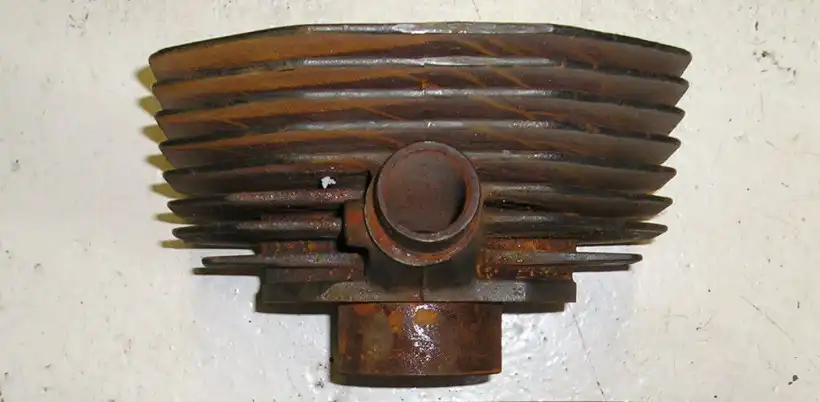
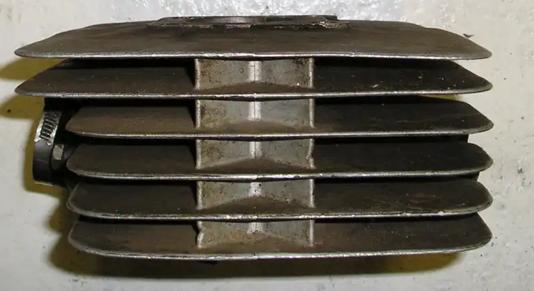
The first thing to know is there are cast iron cylinders and aluminum cylinders. The cast iron cylinders (photo A) have short cooling fins and were used on the 1968 thru 1971 Sachs engines. The Aluminum cylinders (photo B) have large cooling fins and were used on 1970 thru 1975 Sachs engines. The cast iron and aluminum cylinders are interchangeable in that they both use the same bottom end. The 100 and 125 cylinders are also interchangeable in that they also share the same bottom end. The thing to keep in mind if you want to switch from cast to aluminum (or vise versa) is that the cast requires 4 short mounting studs and the aluminum requires 4 long mounting studs.
There is only 1 style of stock cast iron cylinder and these are available as 100cc or 125cc.
The aluminum cylinders however come in 3 styles and are available as 100cc or 125cc. It is important to know the differences between these for the bike application they will be used on.
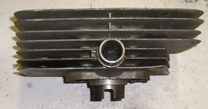
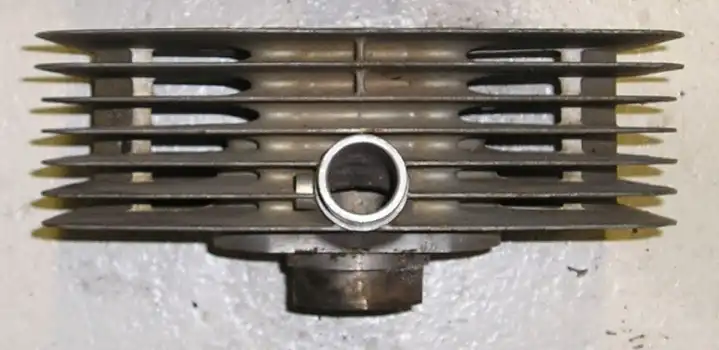
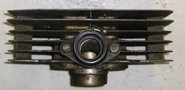
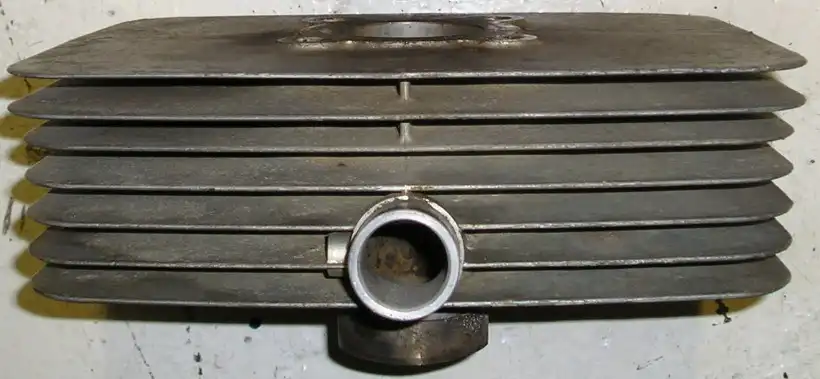
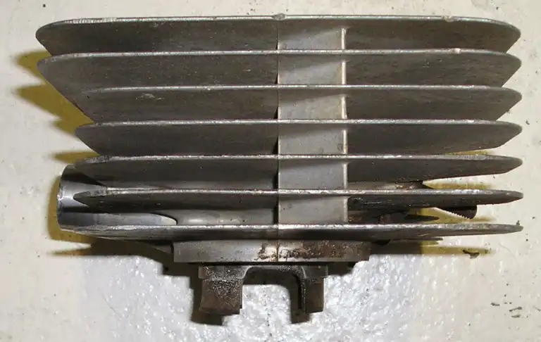
Photo “C” shows an alloy cylinder with the bottom 3 fins “cut off” on the right side. These are used on Sachs engines that use a side mount exhaust pipe. These are what are required on the Penton “steel tank” bikes that have the exhaust pipe mounted on the right side of the frame. This cylinder shown is a 100cc. If you look at the bottom of the cylinder sleeve, you will see a slot in it in the front. This is the quick way to identify a 100 from a 125 cylinder.
Photo “D” shows an alloy cylinder with no cut fins and are commonly referred to as “full” fins. These are used on Sachs engines that use a down pipe or an up and over pipe. These are what are required on the Penton 1972 thru 75 CMF bikes where the exhaust pipe goes up and over the cylinder head.
Photo “E” shows a Sachs “D” cylinder that has “full” fins and was available from Sachs in 1975. These cylinders were available on the 1975 Penton 125 bikes.
Looking at this photo you will see a difference on the intake. Instead of having an alloy “snout” to mount the carb, it has a removable rubber manifold to accommodate a Bing 28mm or 30mm carb. There are slight porting changes in these cylinders giving them more horsepower output. These cylinders are highly sought after for vintage racing. The way to tell the difference between the “D” cylinder and the earlier aluminum cylinders is the “extra” v-shaped spacers in between the cooling fins as shown in photo “G”. I have seen many of the early cylinders where the intakes were machined out to bolt on a reed cage or a rubber mount for a Mikuni carb. So be sure to look for the v-shaped spacers as the proof that any Sachs aluminum cylinder that you are looking at is indeed a “D” cylinder. As far as I know, these only came as 125cc cylinders.
What's the Difference
by Alan Buehner
The purpose of the article is to take the confusion out of identifying the different type of pistons and style of rings used in the Sachs engines.
When the Sachs engines were assembled and shipped from the Sachs factory, there were two type of cylinders provided, cast and aluminum.
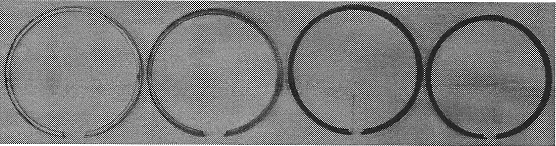
From 1968 to approximately 1970, cast iron cylinders were installed. The pistons used in these came with an "L" ring that was positioned below the top edge of the piston (see photo A). They also came with a square ring a few millimeters below that. Both of these rings were a dull finish that look like they are aluminum.
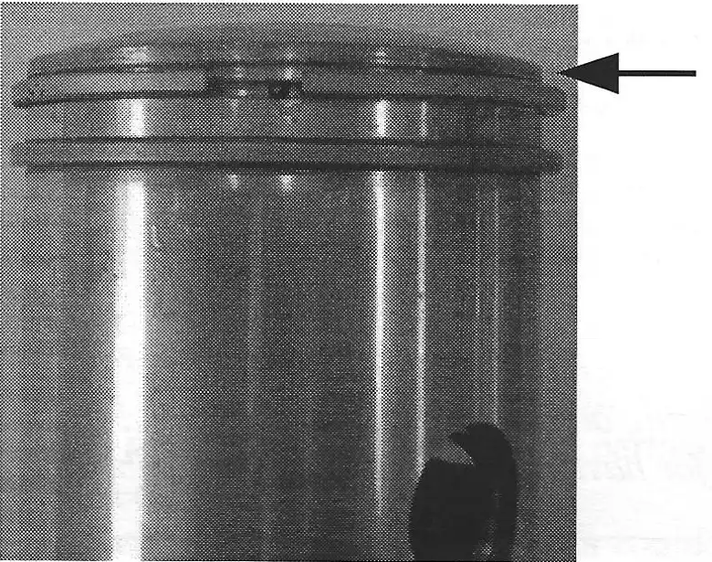
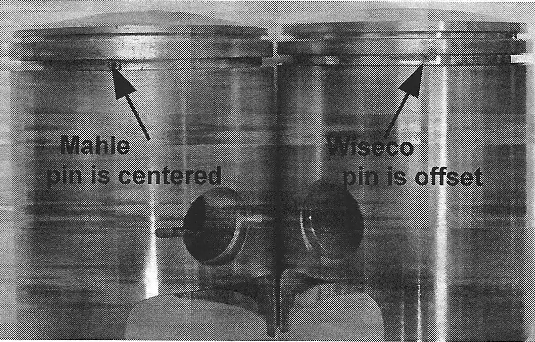
Aluminum cylinders were used on engines starting in 1970. The pistons used in these were Mahle pistons that came with a thin, shiny steel "L" ring on the top edge of the pistons and a shiny steel bottom ring below it. These are what are shown in the parts lists. There were aftermarket pistons made by Mahle and Wiseco (not shown in the parts lists) that use a black carbon "L" and bottom ring. These rings look alike but there is a difference in the bottom rings. The ends of the rings are cut differently to fit the locating pin inserted into the pistons (see photos B and E). It is important when ordering rings to know these differences because on the Mahle pistons, the black carbon rings are thicker and will not fit the pistons designed for the shiny steel rings.
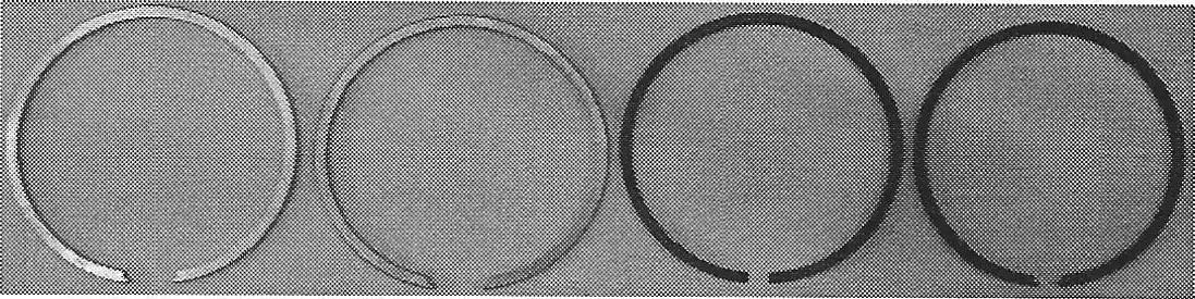
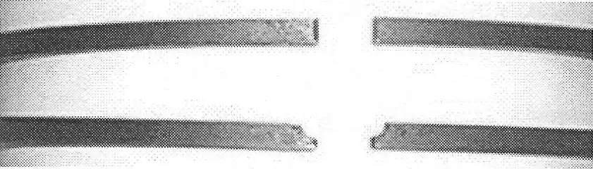
Top - Mahle black carbon, ends cover pin
Bottom - Wisco black carbon, ends surround pin
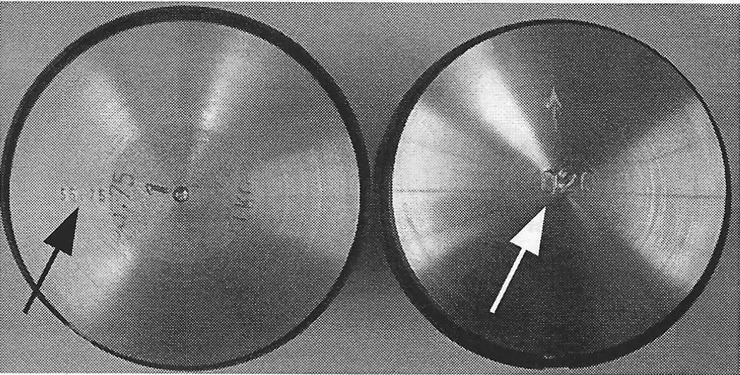
The Mahle pistons can be identified by the pistons size (in millimeters) stamped on the top (see photo F). The Wiseco pistons are stamped with an arrow (pointing to the exhaust) and sizes stamped with oversize in thousanths (.020, .040, .060 etc). Mahle pistons can also be identified by the name "Mahle" which is cast on the underside of the piston by one of the lubricating holes for the wrist pin. Wiseco pistons have a "W" cast into the underside.
by Alan Buehner
In the last “Tech Tips” (Still Keeping Track – Spring 2012, issue #54) I showed the different styles of intake manifolds used on the KTM cylinder, from 1972 thru 1980. In this issue, I am showing the different style of air boots used on the KTM's from 1972 thru 1980. My intention is to make you aware of the different styles and lengths of boots that are available.
With the introduction of the Chrome Moly Framed bikes in 1972, one style of air boot was created – part no. 51-06-026-200 (see photo “A”) to connect the carb to the fiberglass air box. This was a one-size-fits-all boot used on the 125cc to 400cc bikes up until 1976. Since the mouths of the Bing Carb have different diameters, a rubber adapter was needed for the Bing 27mm carburetors use on 125s – part no. 51-06-029-000 (see photo “B”) and Bing 30-32mm carburetors used on 175s – part no. 52-06-029-000 (see photo “C”), so that the small end of the air boot would fit snug.
In 1976 the new MC5 frame was introduced with an alloy air box that required a new style of air boot – part no. 55-06-026-000 (see photo “E”). The 125's used a 28 or 30mm Bing 84 Carburetor that required the used of a plastic adapter - part no. 51-06-029-600 (see photo “D”)– to fit this new air boot.
In 1977 the new GS6 frame was introduced that used the same alloy air box used on the MC5 frame. The same “straight” air boot was used on the 250s and 400s but 2 new air boots were used for the 125s and 175s. The air boot for the 125 – part no. 51-06-026-000 (see photo “F”) is offset and measures 70mm long. The 175s came with Lectron carburetors and used a large bellows style air boot – part no. 52-06-026-500 (photo not available).
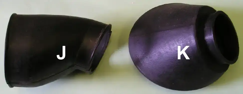
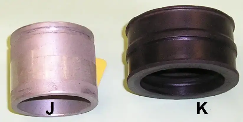
In 1978 both the MC5 and GS6 were equipped with plastic air boxes. This was also the year that KTMs came with a new generation of intake manifolds that were “cocked” and came in different lengths (see Tech Tips in Still Keeping Track issue no. 54). To compensate for these different lengths of intake manifolds, different lengths of air boots were also introduced. The KTM 125 used a 91mm long air boot -part no. 510-06-026-500 (see photo “J” ). The 250 and 400 MC-5s used a 51mm long “cocked” air boot – part #55-06-026-500 (see photo “ I”) to match the “cocked” intake manifolds.
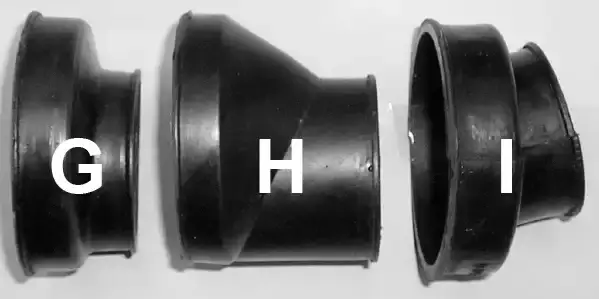
The GS cylinders still used the straight style intake manifolds and depending upon the length of the manifold used, came with a 70mm long boot - part #51-06-026-000 (photo F); a 61mm long boot – part #52-06-026-100 (photo H); or a 35mm long boot – part #54-06-026-500 (photo G).
In 1979 a new frame was introduced – the MC80 and GS80 which replaced the MC5 and GS6 frames. The MC80 and GS80 were the same basic design with the GS80 having a removable rear frame loop. This new frame also came with a new style plastic air box.
The 125GS used a 62mm long air boot – part #52-06-026-600.
The 125MC uses a 91mm long air boot – part no. 510-06-026-500 (see photo “J”).
The 175GS used a 70mm long air boot – part no. 51-06-026-000 (see photo “F”).
The 250 and 400GS & MC used a 35mm long air boot – part no. 54-06-026-500 (see photo “G”).
see photo “K “), mounted on the bottom of the air box.
In 1980 the 175 and 250 used the same air box used on the 1979 frames. They both used the same 62mm long air boot – part #52-06-026-600. However, since the 175 used a smaller carburetor, it used an adapter – part no. 52-06-029-000 (see photo C “ ).
The 125 and 420 used the same air box used on the 1979 420MC80 frames. They both used the same air boot – part #560-06-026-000. However, since the 125 used a smaller carburetor, it used an adapter – part no. 52-06-029-000 (see photo “C “).
In 1981 the 250. 350, and 390 use the 1979 air box but used a “cocked ”51mm long air boot – part no. 55-06-026-500 (see photo “I”).. The 125, 420 & 495 used the same air box and air boot used on the 1979 420MC80 frames.
By Alan Buehner
When KTM developed their engines, they designed their alloy cylinders with bolt-on intake manifolds onto which the carburetors could be installed. The first generation of manifolds (from 1972 thru 1977) were “straight” with an upward angle. The next generation were “cocked” to the side with an upward angle. The following photos will help you to identify and know about the differences about the various manifolds used on the KTM cylinders from 1972 thru 1980.
This is important to know because these different styles of manifolds were used with different styles of air boots which will be featured in the next “Tech Tips” article.
The intake manifold “A” (part no. 52-30-037-000) was used on the first batch of 175 cylinders in late 1971. It was for attaching an Amal carburetor which bolted to the manifold.
The intake manifold “B” (part no. 52-30-050-000) was used on the 175 7 fin cylinders from 1972 thru 1976. It was used for attaching Bing 30 & 32mm carburetors.
In 1977 the 175 cylinders were shortened to 6 fins and the manifold (part no. 52-30-050-500) were shortened and a groove added to accommodate a rubber adapter (part no. 54-30-060-000) for the new Lectron carburetors. The new KTM 125 cylinders came with a similar manifold (part no. 51-30-050-600).
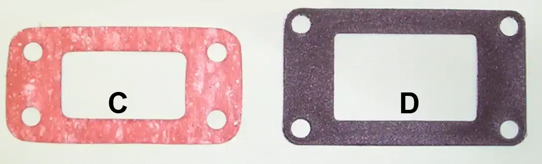
Photo “C” is an intake manifold gasket (part no. 52-30-038-000) used on the KTM 125 and 175s.
Photo “D” is an intake manifold gasket (part no. 54-30-038-000) used on the KTM 250 and 400s.
Looking at the 2 photos, you can see that the opening of gasket “D” is larger than “C” and gives you an idea on size of the intake manifolds.
Item “E” shows the “straight” intake manifold (part no. 54-30-050-300 used on the first KTM 250s in 1973 thru 1976. It was for attaching a 36mm Bing carburetor. With the introduction of the MC5 frame in 1976, a modified intake manifold (part no. 54-30-150-300) was introduced for the modifications of an alloy air box.
A similar looking manifold (part no. 55-30-050-300) was used on the KTM 400s from 1974 thru 1976. It was for attaching a 38mm Bing carburetor. With the introduction of the MC5 frame in 1976, a modified intake manifold (part no. 55-30-150-300) was introduced for the modifications of an alloy air box.
Item “F” shows a “cocked” intake manifold (part no. 55-30-050-400) used on a 1978 KTM 400 GS. It was used to accept the old style “slip on” 38mm Bing carburetor.
1978 KTMs came with a new generation of “cocked” intake manifolds. They came in different lengths to fit either the MC or GS models. They are grooved to accept the rubber boot (item “K”).
Item “G” is a 250 MC manifold (part no. 54-30-150-500).
Item “H” is a 250 GS manifold (part no. 54-30-050-600).
Item “I” is a 400 MC manifold (part no. 55-30-150-608).
Item “J” is a special adapter (part no. 55-30-051-500) for converting a “slip on” 38mm Bing carburetor for use with a rubber boot (K).
Item “K” is a 250 rubber boot (part no. 54-30-060-000) for the 36mm Bing. Not shown is a 400 rubber boot (part no. 55-30-060-000) for the 38mm Bing.
by Alan Buehner
Originally printed in issue #53 of Still….Keeping Track
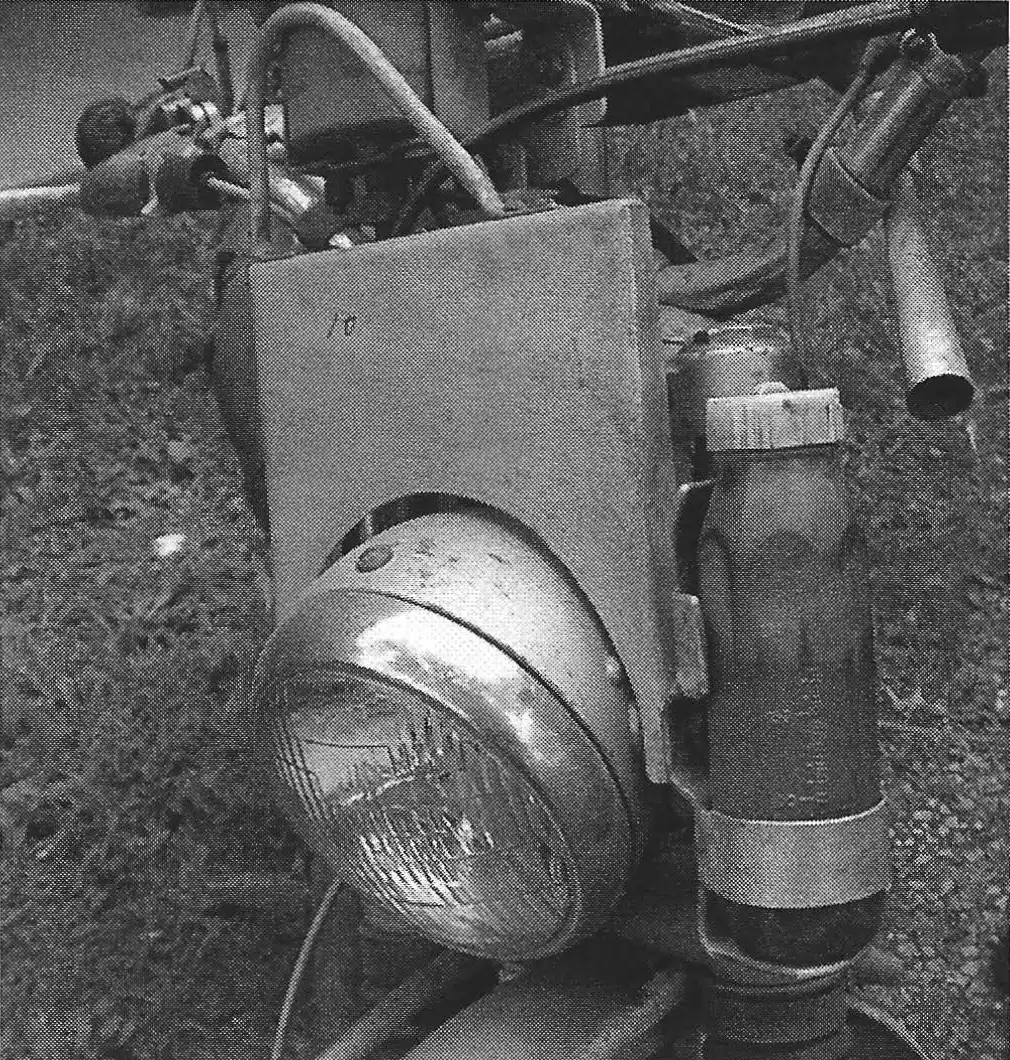
The purpose of this article is to show and identify some of the components on the Penton Short Tracker bike. The basics are the Kenny Roberts designed frame and the KTM 250cc and 400cc engines. The front forks were the Ceriani 35mm found on the 1973 thru 1975 Penton motorcycles. Magura throttle and Power Lever clutch assembly were also installed.