

How to Choose an Engine Case Screw
By Mike Rosso
Originally printed in issue #69 of Still….Keeping Track
Here's a tip on choosing the correct screw length I learned from an old KTM engineer.
To make it as short as possible the engineer gave me a challenge when he scooped up all of the engine case screws that I had neatly arranged and laid out in the correct position on a shop rag as he was watching me reassemble an engine. I put them into the cases and he asked if I was finished and then he swapped two of them. Then he told me that was good but not perfect and then told me how to know the next time. He said there is a standard engineering practice of knowing the position by following the rule of minimum thread engagement when putting a steel screw (or bolt) into a steel thread (steel frame, steel case, etc.,) that you must have a minimum thread engagement of the diameter of the screw or bolt. In other words a 6mm steel screw must engage 6mm of the case or threaded hole, so when you put the screw in you will have 6mm between the head of the screw and the case/hole. If it's an 8mm bolt then there will be 8mm between the head of the bolt and so forth as Mr. John Penton would say.
If you're putting a 6mm steel screw into an aluminum thread as in this case (pun intended) then you need to have two times (2 X) the thread engagement or 12mm and you will see all of the case screws will have 12mm between the heads of the screws even at the dowel pin locations. You can pretty much grab a 12mm wrench and put it at every screw once you place them into the case holes and see the distance the screws stick out.
And for magnesium threads like the KTM magnesium engine cases with steel screws, thread engagement is THREE to ONE or a 6mm screw will need a minimum of 18mm of thread engagement and stick out a minimum of 18mm.
Follow this rule and you won't strip or damage a thread:
- Steel screw to steel thread = 1 to 1 engagement
- Steel screw to aluminum thread = 2 to 1 engagement
- Steel screw to magnesium thread = 3 to 1 engagement
If you keep that in mind (even on non-metric applications) you'll spot when you have the correct or incorrect screw in the right or wrong place or at least know that you screwed up somewhere. Also helps if you're trying to figure out what length fastener to use if it is missing.
by Alan Buehner
Originally printed in issue #72 of Still....Keeping Track
The following articles are from the old “Keeping Track” newsletters on the POG web site.
From #4 March 1973
From #6 May 1973
From #13 Feb 1974
From #2 January 1973
From #14 April 1974

By Paul Danik
Photos by Alan Buehner
Originally printed in issue #71 of Still....Keeping Track
There was a posting on the POG message board asking what should be looked for when considering purchasing a Sachs engine. This was my response.
Whenever I look at any Sachs engine, either in a frame or not, I always pull the ignition cover, even if it looks good from the outside.
Occasionally the cover is damaged from the chain as well as the engine case. I also to inspect the end of the crank. The nut holding the flywheel on is a left hand thread and I have seen a perfectly good looking engine with the end of the crank snapped off from trying to loosen the nut in the incorrect direction. There can also be damage to the end of the crank or the threads from work done in the past, can be a real mess.
Those engines can usually be bench tested as far as shifting, turn the sprocket by hand as you shift the tranny with your other hand. I can't say that you can tell if it is perfect, but you can get a decent indication as to what is going on inside. You can do the shift testing even if the top end is locked up by removing the clutch as mentioned below, then test the shifting.
While you have the ignition cover off you may be able to grab the flywheel and feel if the piston wants to move. I have used chain vise grips tightened carefully around the flywheel to get what seemed like a tight engine to break loose, some oil poured down the plug hole never hurts.
It never hurts to pull the clutch cover off and see just how the oil looks and see if there is any indication of water being trapped inside. While you have the clutch cover off it only takes a minute to pull the clutch off and see just how everything looks and turns. The clutch is held on with a snap ring which is easily removed with circlip pliers. When you lift the clutch off be sure to check that the grooved washer from the three piece bearing under the clutch isn't sticking to the underside of clutch and drops off into wherever those things disappear to.
Doug Wilford always recommended that one does not try to open the bottom oil drain plug as the threads just might come out of the case with the bolt, plus occasionally a person might remove the wrong bolt in the bottom of the engine allowing the kickstarter spring to move and requiring a disassembly of the engine.
In my opinion, a Sachs engine with a good ignition cover, undamaged cases, good end on the crank shaft on the ignition side, clean oil and no sign of water internally, that shifts nicely thru the gears, and with the two ends of the main shaft by the sprocket both intact, is getting to be a rare bird. They are probably worth more that they fetch when comparing what the repairs to a damaged engine would cost.
Hope this helps…
What's the difference?
By Alan Buehner
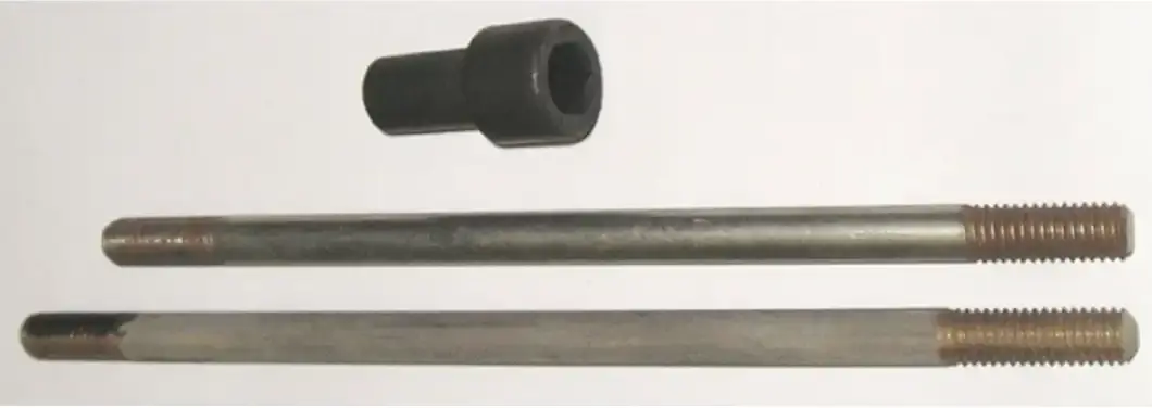
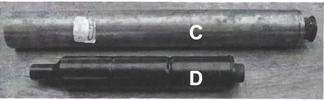
If you don't know any better, you will just assume that all of the KTM 250 cylinder heads are the same and are interchangeable (see photo A). They are interchangeable but not the same. When the 250 engines were designed and produced in 1973, they came with 6-5/8” long cylinder studs (see photo D). They cylinder head was fastened to the stud with a 8mm washer and a regular 8mm nut.
I think that it was some time in 1975 that the engineers decided to modify the cylinder heads and use a special Allen Head cylinder nut (see photo D) to secure the cylinder to the studs. To compensate for this change, the studs were shortened to 6” long (see photo D).
Both styles of heads have the same KTM part number 54-30-006-000 cast into the bottom of the cylinder. So, the only way to identify them is by the diameter of the cylinder stud holes.
If you are missing a cylinder and/ or head, this is good information to know. By measuring the studs on the bottom case (if they are still there) you will know what style of cylinder head that you will need.
If you have the cylinder head, but are missing the cylinder studs, you will then know what size stud you will need and if you also need the special Allen Head nut.
The 6-5/8” long stud is KTM part number 54-30-043-000.
The 6” long stud is KTM part number 51-30-043-000.
Both studs are 8mm in diameter.
The special Allen Head nut is number 55-30-044-000. It is also used on the KTM 400 cylinder heads. It measures 1-1/4” long. The thin part of this nut is 12mm in diameter and is 3/4” long.
Tightening Torques for nuts and bolts
Cylinder studs – 8MM - 12 foot pounds
Cylinder stud nuts - 18-20 foot pounds
8x40 Allen head bolts - 18-20 foot pounds
Tightening sequence – Tighten the Allen Head bolts first so that the cylinder head is centered on the cylinder. Tighten crosswise – left, then right, then bottom, then the top bolt. Finish by tightening the corner stud nuts in a cross pattern.
What to look for:
By Al Buehner
Photos by Lee Buffenmyer & Al Buehner
Originally printed in issue #69 of Still….Keeping Track
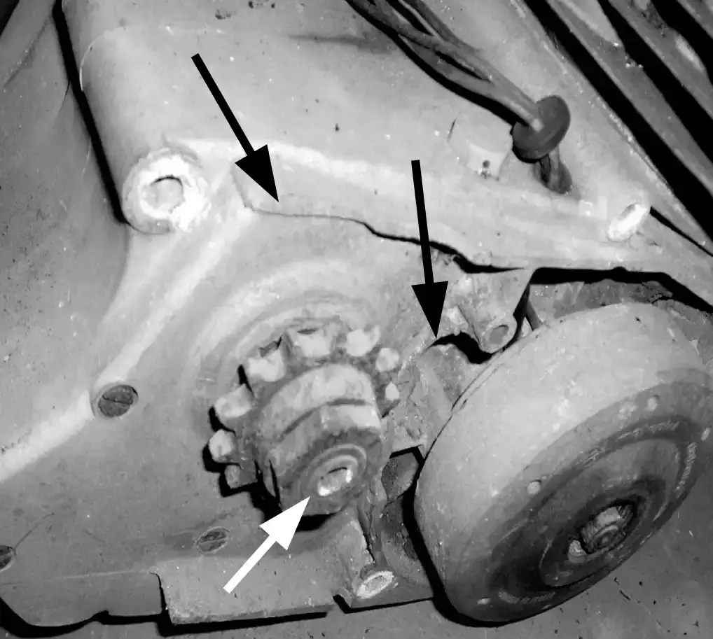
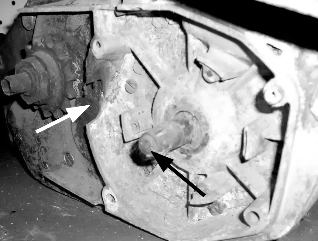
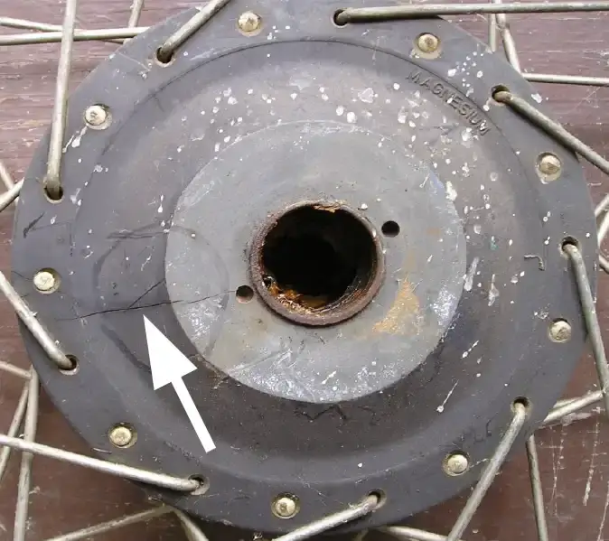
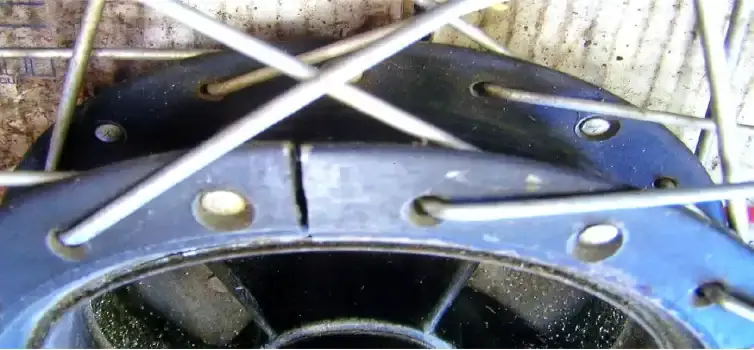
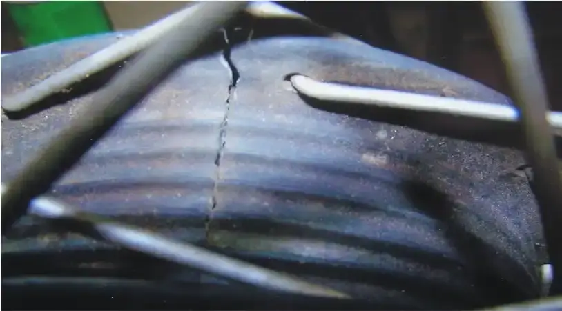
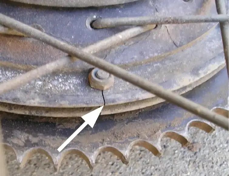
Alloy front hubs were installed on the Penton motorcycles from 1968 thru 1972. In the later part of 1972 and starting with the 1973 model year bikes, the alloy hubs were replaced with magnesium hubs.
From time to time I will get a call from someone looking for a new hub to replace one with a crack in it. The purpose of this article is to show you where to look for cracking in the hubs, be it on your bike when you are doing your maintenance checks or when shopping for a used hub or wheel assembly, or looking at a motorcycle to purchase.
The most common request I get is for a replacement for the black magnesium front hub where the cracking is on the inside around the steel sleeve where the bearings go. This was a problem that KTM became aware of because a replacement front hub was produced (part no. 51-09-010-400) which has a thicker magnesium casting around the bearing sleeve.
What's the Difference?
by Alan Buehner
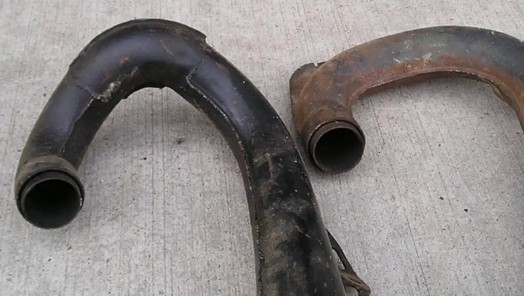
Trying to identify a KTM exhaust pipe can be confusing and frustrating especially if you have no idea what year or size of bike that it came off of. Even if you have several KTM pipes together with no identification, at least you can compare them side to side to try and find some differences.
The 175 and 250 pipes look almost identical. The difference between the two is how the pipes were constructed (welded together).
The 250 is easy to spot in that it has a continuous seam from the header to the back of the cone. It is basically two stamped out halves with a joint seam welded together and the back part of the cone then welded to the front part. (see photo A)
The 175 pipes have three welded together sections. There are the two front stamped out halves welded together, joined to the center cone, which is then welded to the back cone section. (see photo A)
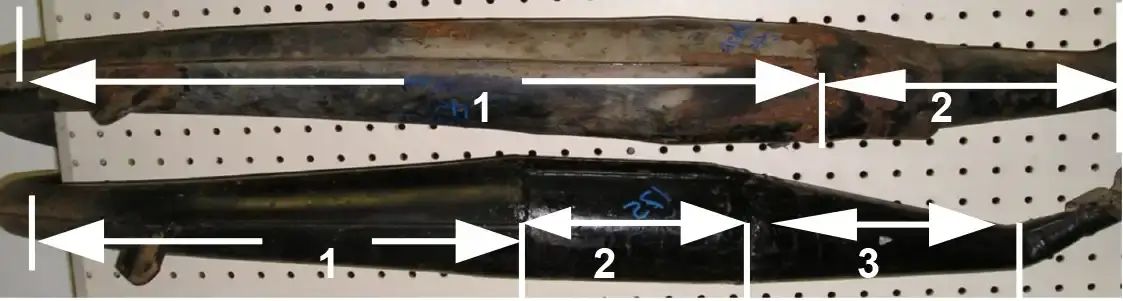
What makes the KTM 400 pipe stand out from the 250 is the curvature of the pipe from the header. The 250 is “J” shaped with a gradual 180 degree curve from the manifold to the expansion chamber. The 400 pipe his two 90 degree sections welded together and then welded to the expansion chamber. (see photo B)
One other thing to help identify a KTM 125 exhaust pipe from a 175 or 250 pipe is the diameter of the opening for the exhaust manifold.
The KTM 125s use a smaller diameter exhaust manifold. Thus, the diameter of the pipe end is also smaller than the 175 or 250. (see photo C and D)
The KTM 175, 250 and 400 all use the same size exhaust manifolds. Their pipe ends are also the same diameter which make them look alike.
The KTM engines from 1973 to 1975 use a straight manifold. The 1976+ engines use an angled down manifold and the neck to the exhaust pipes are angled up to fit these manifolds.
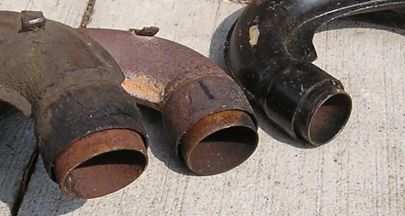
Top left – manifold used on the Sachs 125 engines
Top right –angled manifold used on KTM 125 engine
Bottom left – straight manifold used on KTM 175, 250, and 400 engines prior to 1976.
Bottom right – angled manifold used on KTM 175, 250, and 400 engines after 1975.
GENERAL SERVICE INFO No. 13
by Alan Buehner
The following General Service bulletin was mailed out to Penton Dealers on August 15, 1975 by Penton Imports. It is being reprinted in this newsletter to alert any of our members who have bikes with these forks as to what to look for when servicing them.
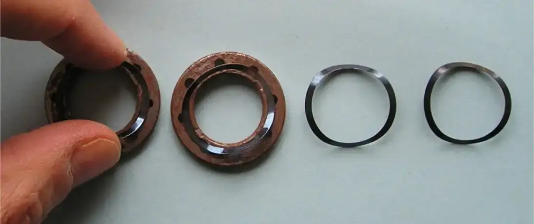
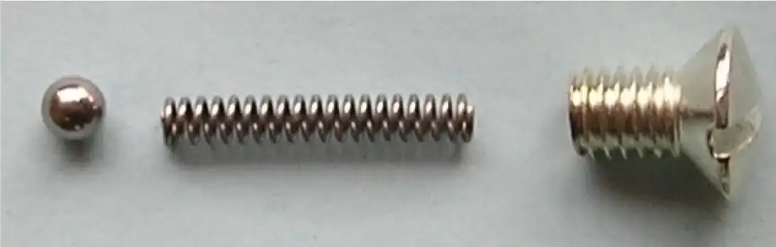
Our riders and a few dealers have recently discovered that the dampening control of the 35mm Ceriani fork can be fantastically improved by replacing a small washer type spring #1-209-0612 and in the case of a fork over a year old, replace the aluminum washer #1-209-0610. The original factory springs have always been heat treated wrong for lasting control. We have now had made special heat treated spring washer that do the job indefinitely.
This spring washer is cheap and can be replaced very easily by gently pinching the two high edges and it will remove like a charm. Replace the new ones the same way and do your best to center the springs and the aluminum washer spacers. If necessary, along with the cleaning, polishing of the ball check in the fork tube caps, you can not go wrong in noticing a great difference and improvement in the total suspension of your bike.
This condition in the front fork has been bugging a lot of riders for a long time and 50% of the time they have been thinking it is their rear shocks. One last comment on the ball check valves in the fork caps. When cleaning and polishing these balls, make certain the little vent hole is open through the cap. This takes a very small drill bit or wire to clean. Always after washing your machine, I recommend spraying LPS or similar type rust preventative in the small vent hole. This is insurance on always having a beautifully working fork that won't leak. We have the washers and aluminum spacers in stock, and believe me they are rightly cheap for the results.
no. 1-209-0612 wave washer spring
no. 1-209-0610 aluminum washer
These wave washer springs and aluminum washers are used in the 1973 to 1976 Ceriani 35mm forks. In 1976 a new valve set #1-844-065 was used in the leading axle Ceriani forks to replace the old style valve set. This new valve set can be used as a replacement valve set in the 200mm Ceriani forks.
Please NOTE: The #1-209-0610 washer is steel not aluminum as printed in the service bulletin.
What's the Difference
by Alan Buehner
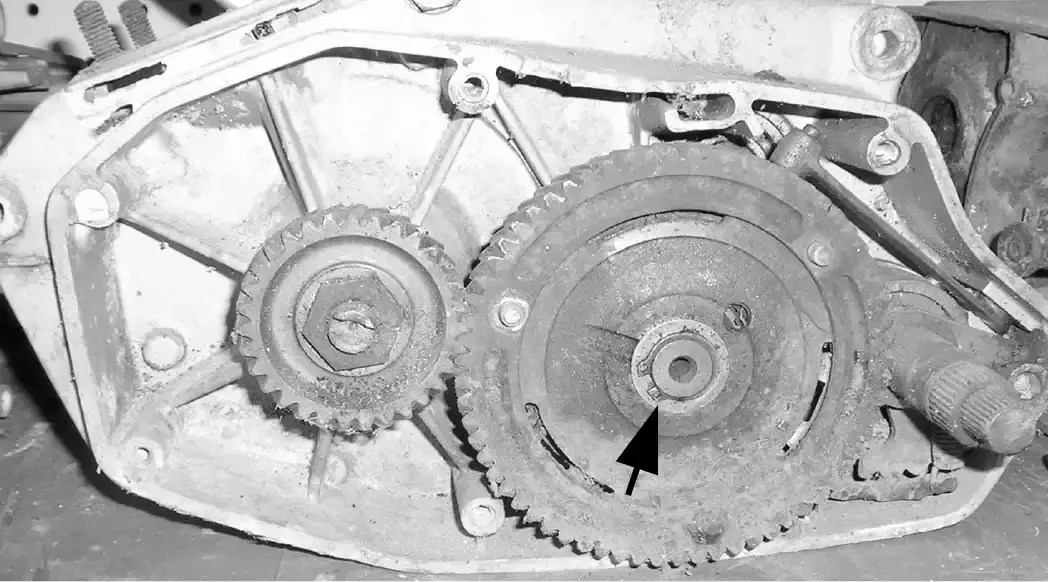
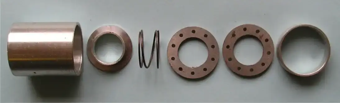
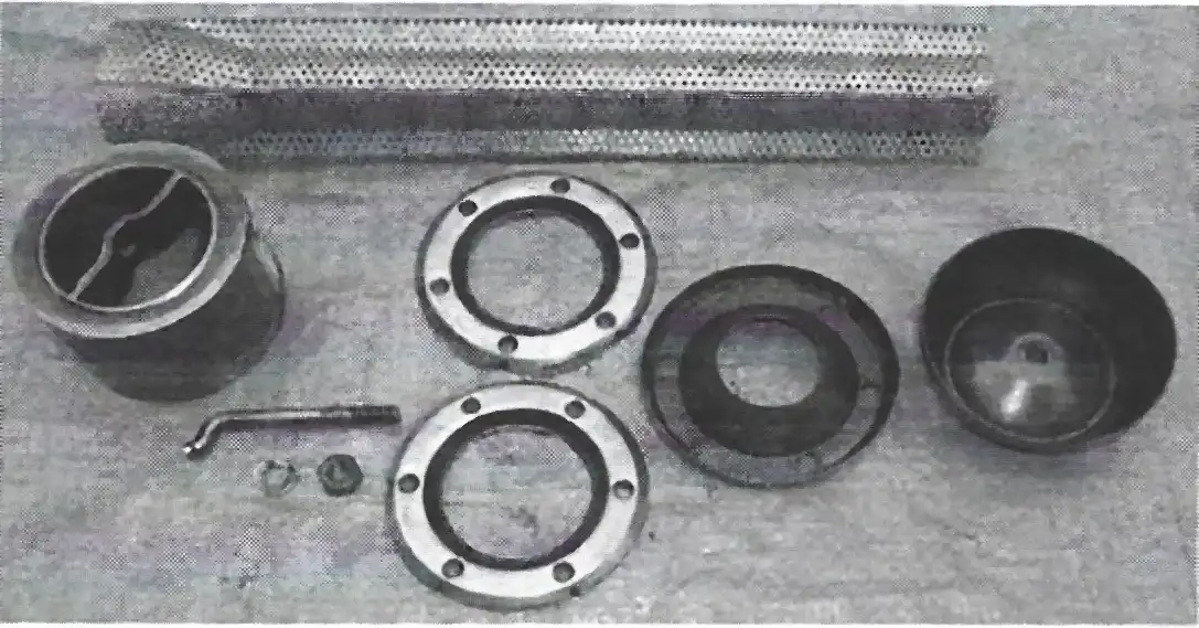
I recently received a phone call from a customer who was looking to transfer the inside components of his Sachs 5 speed engine case of which the outside, ignition side was broken to the inside of a newly purchased used Sachs 5 speed engine case. In trying to do the switching he discovered that bearing for the main shaft was a different size diameter and he called me to see I had a bearing to fit it. I carry both sizes of bearings in stock, however the inside diameters are also different. There are also 2 different size main shafts that correspond to these bearings.
The customer wound up keeping his old clutch side half and using the new/used ignition side half. Both cases were the “A” cases that used the larger diameter crank.
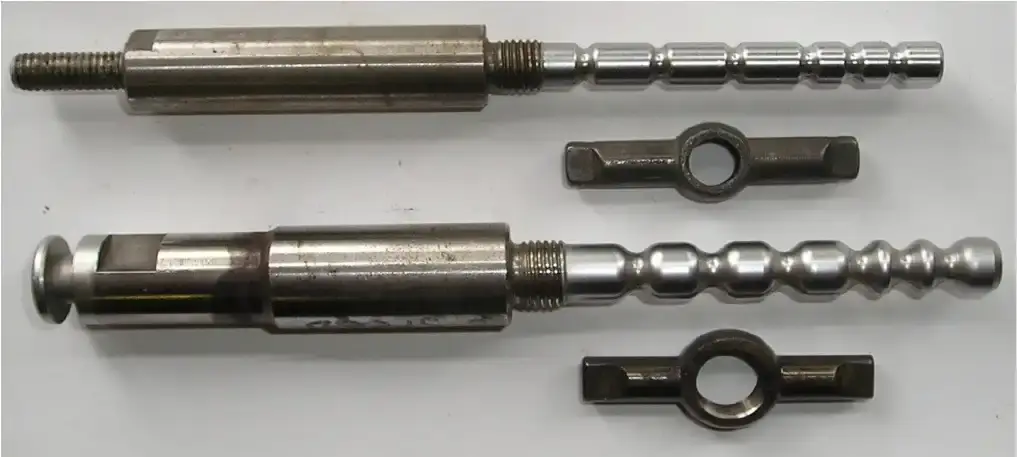
The purpose of this article to alert everyone that is involved with the Sachs engines that there is a difference with the Sachs “A” engines with regard to the main shafts and show you just what the differences are.
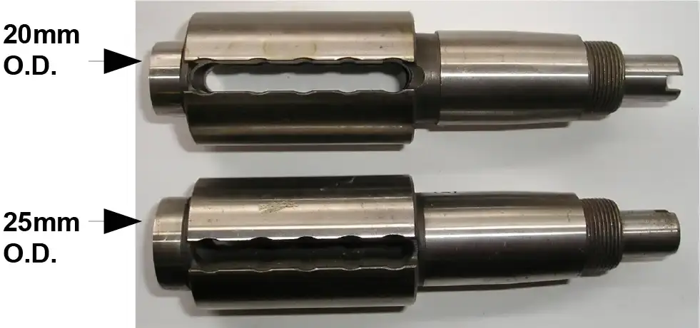
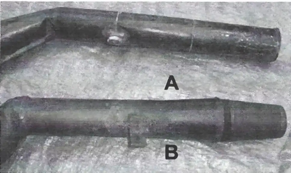
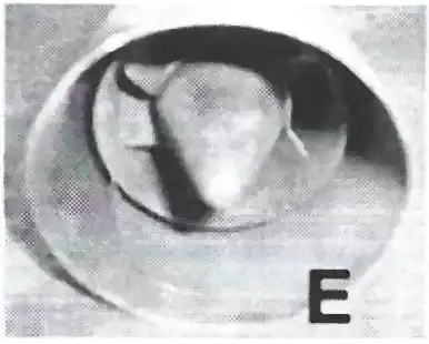
Photo “A” shows the two different 5 speed main shafts The top main shaft is for the early Sachs engines that use the 8mm selector rod and key (as shown in photo “B”. The lower main shaft uses the 10mm selector shaft and key. As you can see, from the side they look almost identical except if you compare them at the ends.
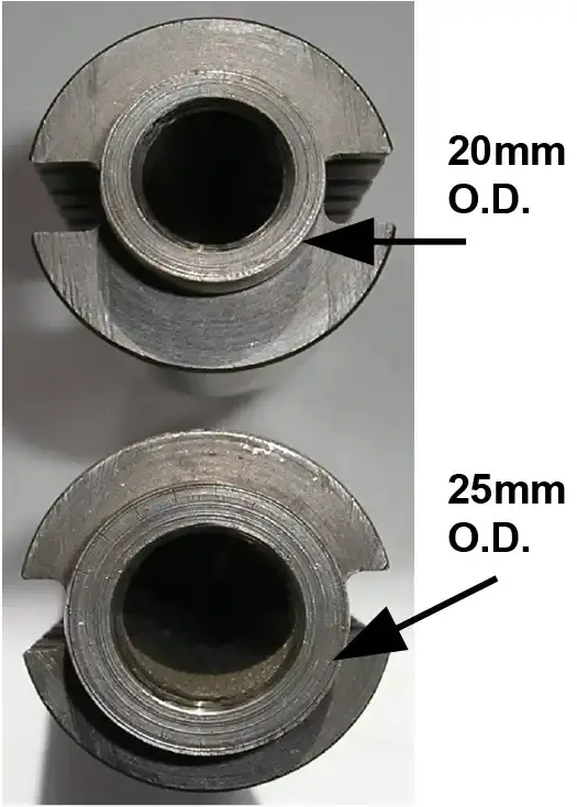
The bearing end the main shaft that uses the 8mm selector shaft measures 20mm O.D. The bearing end the main shaft that uses the 10mm selector shaft measures 25mm O.D. as shown in photo “C”.
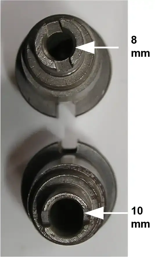
Photo “D” shows the sprocket end of the main shafts The top main shaft has a 8mm I.D. And the bottom main shaft has a 10mm I.D.
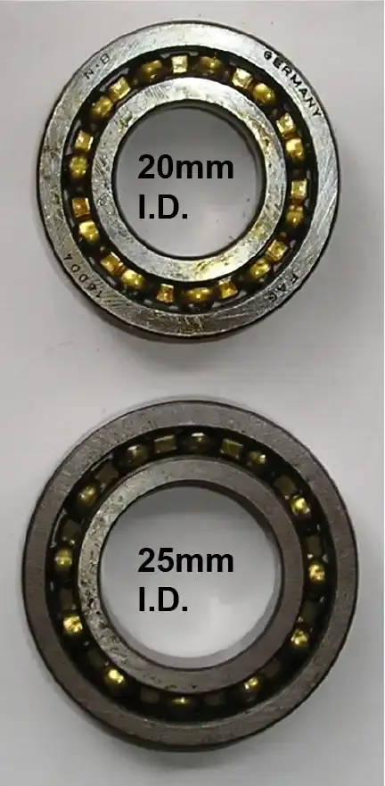
Photo “E” shows the 2 bearings. The top bearing is a 16004 bearing, part number 0232-130-001, and measures 20mm I.D. X 42mm O.D. The bottom ball bearing is a 16005 bearing, part number 2732-006- 000, and measures 25mm I.D. X 47mm O.D.
8mm Mainshaft is shown on top – part #0637-102-000
10mm Mainshaft is shown on bottom – part #0637-102-100
8mm Selector shaft and key is shown on top.
10mm selector shaft and key is shown on bottom.
Top one uses 8mm selector shaft and key
Bottom one uses 10mm selector shaft and key
Top one uses 8mm selector shaft and key
Bottom one uses 10mm selector shaft and key
Top one is a 16004 bearing for the mainshaft that uses the 8mm selector shaft and key
Part number 0232-130-001
Bottom one is a 16005 bearing for the mainshaft that uses the 10mm selector shaft and key
Part number 2732-006-000
What's the Difference
by Alan Buehner
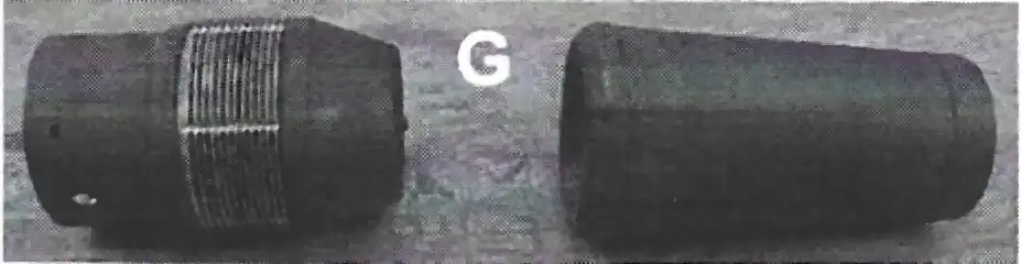
Prior to the 70's, silencers were not required but as motorcycle racing exploded, especially moto cross, rules were adopted requiring silencers on all race bikes and inventors rose to the demand to meet the needs. In the early 1970s there were many aftermarket silencers that were being sold. Many of these were bolt-on style to fit over the exhaust end “stingers”. There were also some weld-on styles.
The Penton/ KTM motorcycles all came with factory equipped silencers in their exhaust pipes except for the 1968 models which had straight “stingers”. These early pipes were modified with resignators off of VW Beetles by cutting off the stinger and welding on the resignator. All the other exhaust pipes came with a shroud covering the stinger and either a baffle or packing was inserted and held in place with an exhaust end. Unfortunately the shrouds did not hold up too well in the woods and on the race tracks resulting in them becoming smashed and dented. Plus there was a tech tip in one of the Penton publications recommending that the shroud be cut off to obtain more power. This recommendation was well spread in that there were very few bikes to be found today with the shrouds still intact.
There were 3 basic types of aftermarket exhausts used on the Penton/ KTM bikes. The X-Duser, the Super Trapp, and the J&R Krizman brands. All three of these are patented and are U.S. Forest Service approved.
The first aftermarket silencer that I had on my Jackpiner was an X-duser. It was a round, sauce pan shaped thing with a removable lid. It bolted to the end of the pipe with rubber lined adapter that came in assorted sizes to fit the different diameter stingers. It looked a little strange but worked very well. Unfortunately I did not have a sample to take a photo of and show in this article.
The J&R Krizman exhaust was advertised in the Hi-Point Accessories catalog beginning in 1975. It was promoted in the ad as a “new trick power valve” that was easy to install, just cut the expansion chamber at the place where the Power Valve and pipe diameter match and weld it on.
This is an interesting device in that it has a spring loaded end piece that expands outward to relieve the back pressure when the rpms of the engine build. It is unknown how many of these units were installed. They are rarely seen on vintage Penton/ KTMs before restorations.
The most popular aftermarket exhaust was the Super Trapp which used a series of removable discs to power tune the exhaust for more or less power. These came in many different styles to fit 2 and 4 stroke engines and were basically bolt-on or weld-on units.
What's the Difference
by Alan Buehner
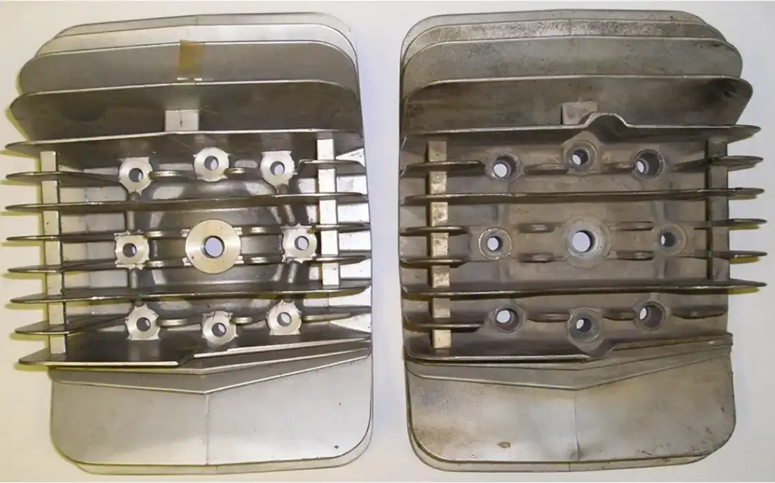
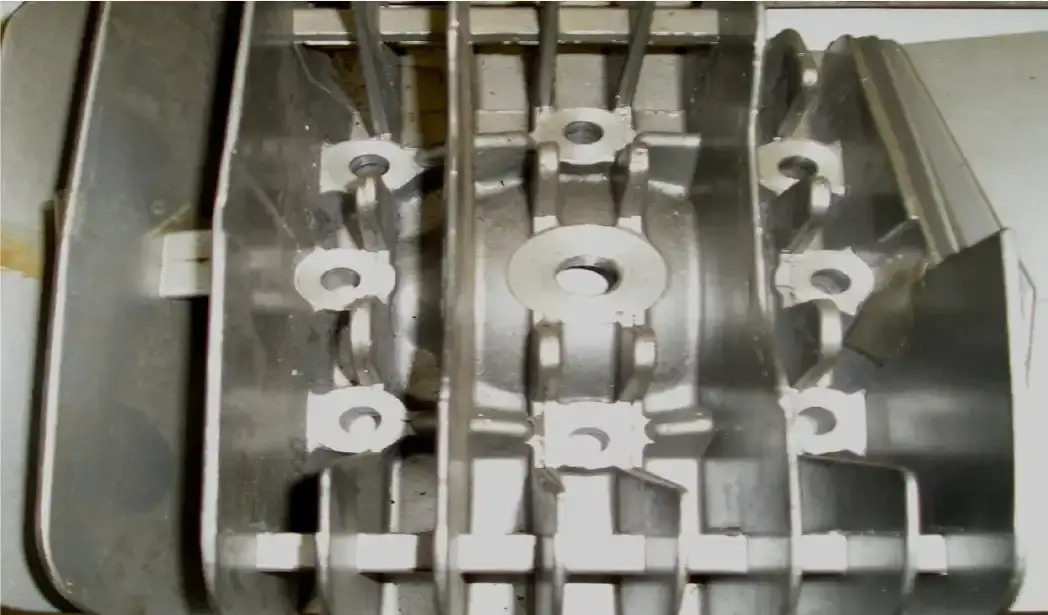
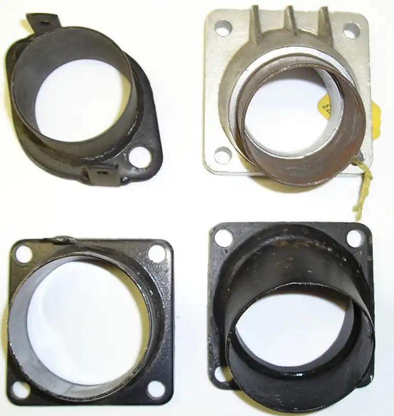
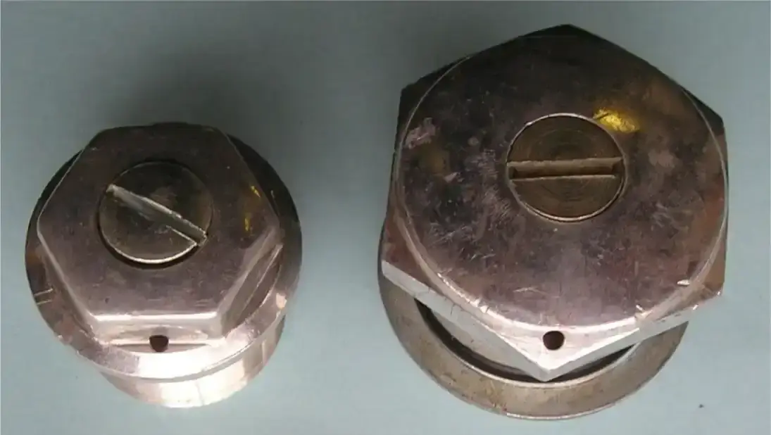
There were 3 generations of KTM clutch case covers that were used on the KTM engines from 1972 thru 1980.
FULL CLUTCH CASES – as shown in Photo “A” – were used on the 1972-73 KTM 175 engines and also on the 1973 KTM 250 engines.
CONTOURED CLUTCH CASES – as shown in Photo ”B” – were used on all the 1974 KTM engines. The smaller size reduced the amount of oil required in the cases and most likely allowed the clutch baskets to spin quicker. Note the gusset on the bottom left. This is part of an internal channel to help direct oil flow away from the clutch basket as it spins.
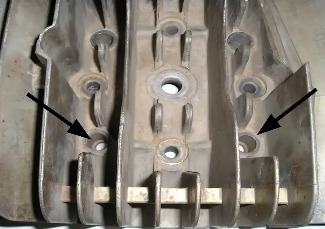
MODIFIED COUNTOUR CLUTCH CASES – as shown in photo “C” - were used on all KTM engines from 1980. The lower right corners were cut-away (as shown by arrow in photo) to allow the engine cases to fit around the left foot peg on the redesigned frames. Note the gussets on the top right and bottom left. These are part of two internal channels to help direct oil flow away from the clutch basket as it spins.
The extra top gusset was added in 1975.
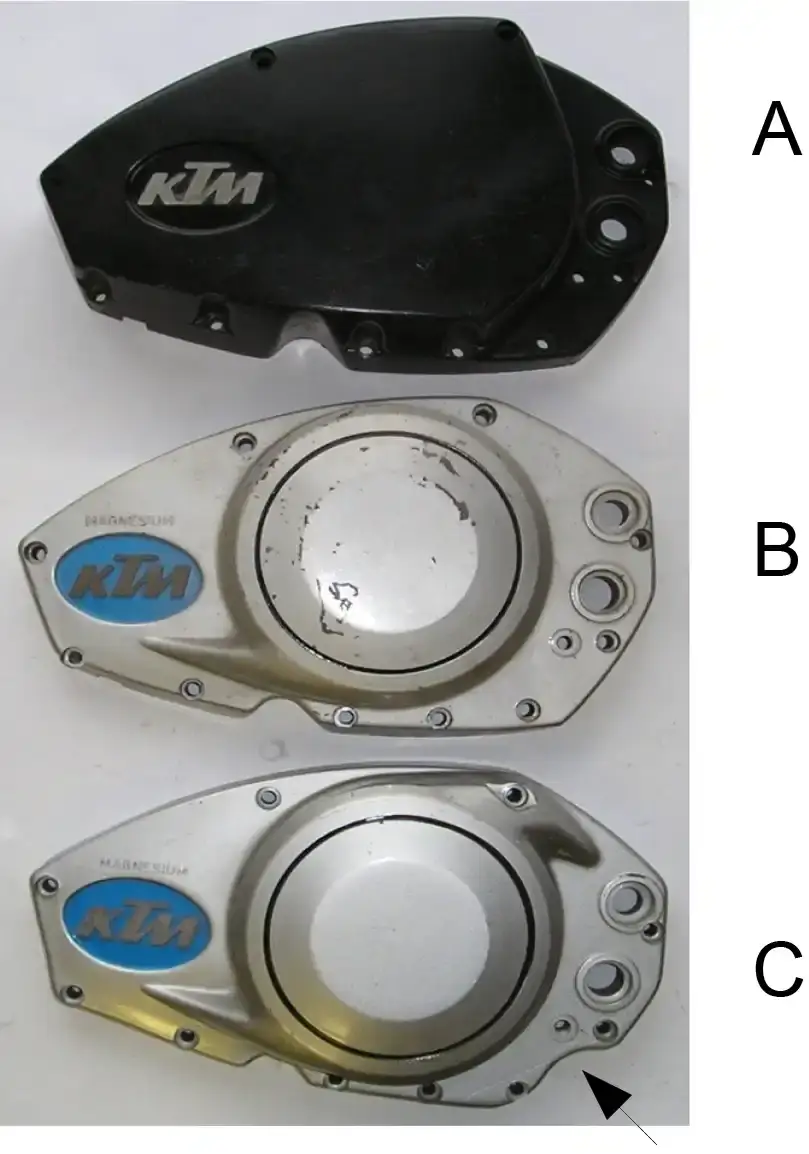
There were 2 versions of each generation of the clutch case covers.
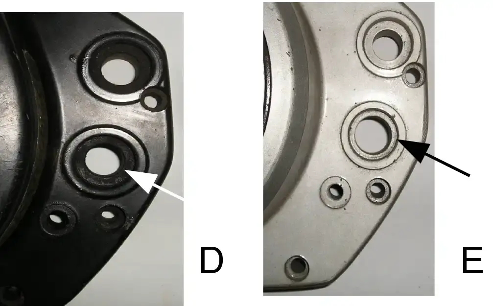
The first version has a 14mm opening for the14mm kick starter shafts used on the 125 and 175 engines (as shown in photo “D”). These were also used on the early 1973 black 250 engines.
The KTM part number for these cases are:
51-30-001-010 – full case
51-30-001-110 – contour case with lower gusset
51-30-001-510 – contour case with dual gussets
510-30-001-610 – contour case with cut-a-way corner
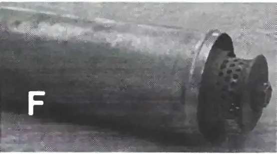
The second version has a 17mm opening for the 17mm kick starter shafts used on the 250 and 400 engines (as shown in photo “E”).
The KTM part number for these cases are:
54-30-001-110 – contour case with lower gusset
54-30-001-510 – contour case with dual gussets
540-30-001-610 – contour case with cut-a-way corner
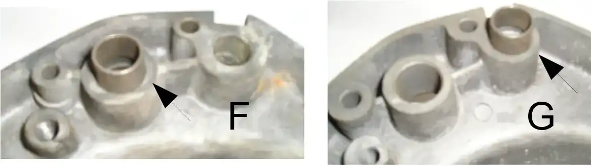
Something to be aware of is that the engine cases and the clutch case covers share a steel alignment sleeve with a measurement of 17mm o.d. X 15mm i.d.
On the 1972 thru 1977 engines, this sleeve is positioned on the kick starter hole for the KTM 125 and 175 engines (as shown in photo “F”). For the KTM 250 and 400 engines the sleeve is positioned on the shifter hole (as shown in photo “G”). The location of this sleeve could cause problems if you are looking for a replacement cover.
On all the 1978-80 engines this sleeve is positioned on the shifter hole.