

Lectron Carb Brochure
Click on images to enlarge as slideshow.


Profile and Ovality Explained
by Kevin Bailey at Wiseco
Originally printed in issue #80 of Still….Keeping Track
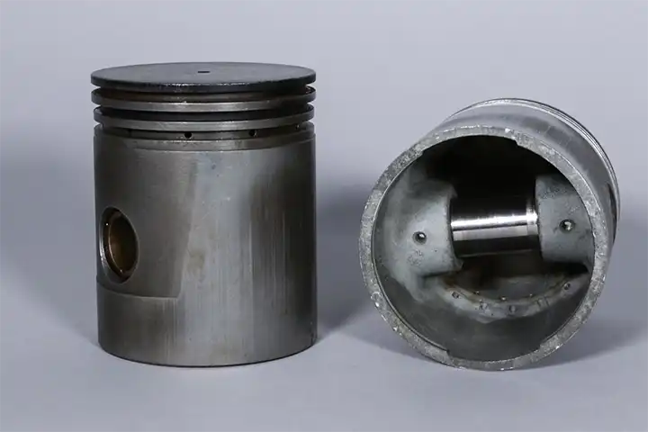
Profile and ovality are two main characteristics of piston design. Here we'll take a look at why pistons are designed to not be perfectly round.
When you look at a piston, it is easy to think that they are a perfectly round, cylindrical shape. After all, they go into a round hole (the cylinder!) So why shouldn’t they also be round?
The fact is, the external shape of a piston is very sophisticated. An internal combustion engine is a hostile environment where combustion gasses can reach dangerous temperatures, and there could be port windows and surface undulations from uneven cylinder cooling. Designing a piston that is optimized for combustion chamber conditions is an important challenge.
Throughout the years, piston materials and design characteristics to compensate for expansion under heat have evolved. Forging pistons out of aluminum provides great strength and durability, but it must be used in the correct design to properly optimize the performance of the piston.
There are two major characteristics of piston shapes: profile and ovality. Wiseco's Product Manager and long time engineer Dave Sulecki commented on these piston characteristics: “Piston profile and ovality are one of the most important features of a piston, these really determine not only how the piston will wear over time, but also how well the piston can perform. When the engineer calculates the piston to cylinder clearance, this is only the beginning of a complex determination of the final piston geometry."
Profile
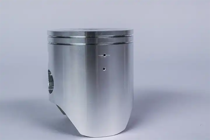
If you roll a piston across a flat surface, you'll notice it does not roll in a straight line. You are observing characteristic number one: profile. Because aluminum conducts so much heat, pistons are designed with a taper -- the top of the piston, near the crown, is a smaller diameter than the bottom of the piston, near the skirt. The skirt of the piston actually is designed with what is called a barrel shape, illustrated below. This is beacuase temperatures near the dome of the piston vary from the temperatures at the skirt of the piston, resulting in different levels of expansion. The tapered shape allows the piston to expand as heat is applied, so the piston does not bind in the cylinder bore. The higher the temperature, the more the piston will expand. The design challenge then becomes calculating the degree of taper. Too tight of clearance can induce scuffing or seizure from heat expansion, while too loose of clearance can introduce noise from piston rock.
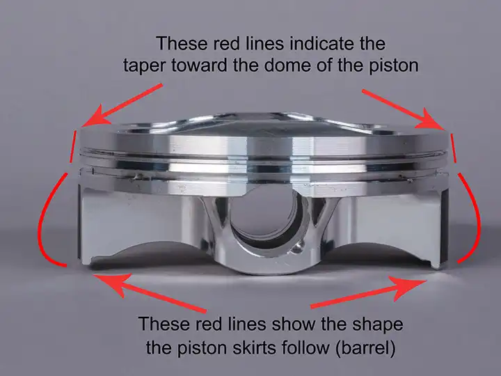
"The piston profile is critical to how the piston will support itself as it reciprocates in the cylinder bore. For example, the piston profile must help hold the piston vertical in the bore during combustion; imagine any excess leaning of the piston would allow piston rings to become “unseated” and not seal properly against the cylinder wall," elaborates Sulecki.
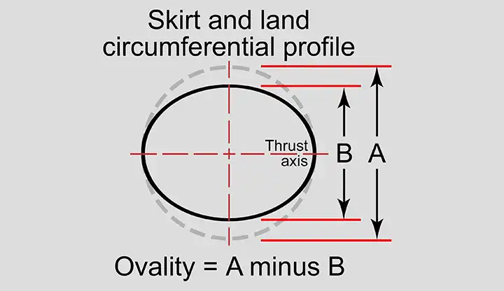
Ovality
As you roll the piston across the table, you will also observe the piston rising and falling in a “hump-hump-hump” motion, much like a wheel that has a flat spot. This characteristic is called ovality, also known as camming. In the simplest terms, ovality means that the piston is smallest in line with the wrist pin bore.
As the engine begins its movement, the connecting rod is not moving only up and down, but due to the rotation aspect is simultaneously moving sideways. This action from the connecting rod and the motion of the crankshaft place load forces on the piston along the plane of the connecting rod inline with rotation (known as the “thrust axis”). To allow the piston to move freely with this sidelong force, the piston cannot be perfectly round, or it would bind in the round cylinder bore. By applying ovality to the piston, the piston is free to move up and down as needed. The challenge in design is applying the proper amount of ovality. Too little ovality can cause the piston to contact the cylinder wall nearest the end of the piston pin, while too much ovality can cause the piston to ride too heavily against the cylinder wall along this “thrust axis.” Too much load along the thrust axis can result in heavy scuffing or seizure, when the piston breaks the oil film barrier and contacts the cylinder wall directly.
Dave Sulecki commented on ovality,
"Ovality is an unknown thing, when most people look at a piston they think it is round, and to the naked eye this must be the case. However, take a new two stroke piston and roll it across the table and what happens? You will see the uneven “hump, hump, hump” as the piston rolls in a large arc…you are seeing both the profile (the “cone shape” of the piston”, in combination with the ovality as the piston rolls unevenly. Ovality is necessary for the piston to move up and down in the cylinder bore, as the crankshaft and connecting rod try to force the piston upward, and combustion forces the piston downward, ovality allows the piston to move without binding in the round cylinder bore."
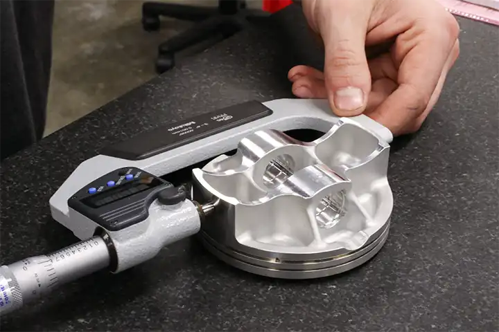
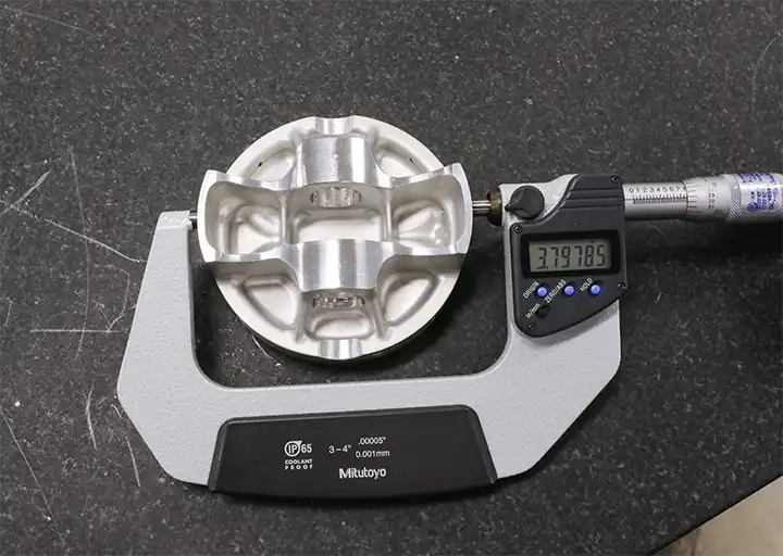
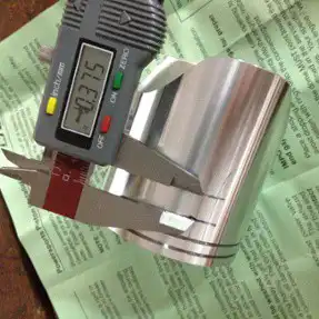
Ovality is a key detail to remember when measuring piston size. The piston must be measured at the bottom of the skirt, 90 degrees from the wrist pin hole to reach an accurate measurement.
When measuring piston diameter, be sure you’re using the proper tools. Do not use calipers to measure your piston(s), as you won’t get an accurate measurement. The most accurate tool to use is a set of outside diameter micrometers.
Some Wiseco pistons feature proprietary skirt coatings such as ArmorGlide or ArmorFit, which are designed to reduce wear, provide smoother and quieter operation, and are applied to last for the life of the piston. With certain skirt coated pistons, piston-to-wall clearance measuring specs will change, so be sure to read the instructions that come with your piston(s).
by Joe Lehr
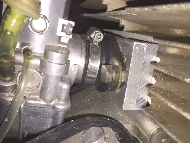
I purchased the manifold shown in the attached picture online. Many vendors offer the part and you can find it by searching for p/n: MVM28200.
The spacing of the mounting holes is a bit off so I cut the aluminum to form slots which make alignment pretty easy. I have had the pictured flange on the original cylinder since October 2011. It is working well and want to share the info with others that need a solution.
by Wiseco Performance Products
Originally printed in issue #78 of Still....Keeping Track
Find out how to relieve an exhaust bridge and drill lubrication holes in 2 stroke applications, so you can get the most out of your piston!
When you order a new Wiseco 2-stroke piston and open up the box and read the instructions, you might see something like “follow these steps to drill the lubrication holes.” There’s no doubt that the thought of drilling holes in your new piston can be scary and intimidating. But not to worry! We’ll get you through it right here with all the information you need and a step-by-step. Relieving the exhaust bridge and drilling lubrication holes is a common part of the 2-stroke top end replacement process, but the importance of performing these steps is unrealized by many and neglected too often.
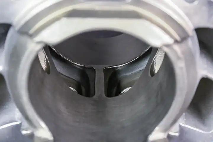
So, what is an exhaust bridge?
First things first, not all 2-stroke cylinders have an exhaust bridge. So if your cylinder does not have one, drilling holes in your piston is not necessary.
The exhaust bridge is the thin strip of metal that separates the exhaust ports in the cylinder. Whether you look into the exhaust ports through the exhaust outlet or through the cylinder bore, if you see a thin metal wall separating your exhaust ports, that is your exhaust bridge. For the purpose of installing a new Wiseco piston, the area of concern is the edge of the exhaust bridge on the inside of the cylinder bore.
The exhaust bridge is the edge of the wall separating the exhaust ports on some 2 stroke cylinders.
Why do I need to relieve the exhaust bridge?
Now that we know what the exhaust bridge is, it’s important to understand why we feel this machine work is essential to replacing a 2-stroke top end. The most heat in your motor is generated from combustion in the cylinder during normal operation. Specifically, the exhaust port(s) of the cylinder are exposed to the most heat because this is the only way out for the hot gas produced during combustion.
This means that under normal running conditions, your piston and your exhaust bridge are constantly under the pressure of extreme heat.
Wiseco pistons are made from forged aluminum, which offers more strength and reliability, but also expands faster under heat than an OEM cast piston. The exhaust bridge will also expand more than the rest of the cylinder because it is such a thin structure. The lack of material makes it harder for heat to dissipate before it affects the aluminum and causes expansion.
Expansion under heat is normal, but must be compensated for to make sure you get the most life and best performance out of your top end. Relieving the exhaust bridge simply means taking a small amount of material off the face the bridge in order to make room for expansion. If there was no extra tolerance, the exhaust bridge would expand past the cylinder wall once your motor heats up. This leads to scoring on the piston as it comes into contact with the exhaust bridge, especially as the piston expands at the same time.
Relieving the Exhaust Bridge
Now that we have some understanding established, let’s go through how to get it done. As always, if you don’t feel comfortable doing this work, this can commonly be done by the shop performing your cylinder work. If you have the rights tools, this can be done in the garage on cast iron and steel cylinder bore liners. We recommend using a die grinder with a small sanding roll to gently remove 0.003” of material off the cylinder wall face of the exhaust bridge.
After the material is removed, the machining must be blended with the rest of the cylinder wall at the top and bottom of the exhaust bridge. You want to make sure there’s an easy slope for the piston ring to slide over when entering and exiting the exhaust bridge relief. If your cylinder is lined with Nikasil, this process will not work because that material is too hard. Your exhaust bridge must be relieved before being lined with Nikasil to achieve the same result. Check with the shop you choose for your cylinder work if you are unsure.
Why do I need to drill holes in my piston?
Relieving the exhaust bridge will make sure there’s no expansion past the cylinder wall, but we still want to make sure we keep the heat as low as possible. With small holes drilled into the skirt of the piston, oil underneath the piston will makes its way through the holes, and lubricate the contact point between the piston and exhaust bridge. Better lubrication means less friction, and less friction means less heat, which is what we want to make sure we don’t have any abnormal wear.
Drilling Lubrication Holes
Make sure you have the instruction sheet that came with your new piston. This drilling information can also be found there, complete with a visual diagram.
Be prepared with your instruction sheet.
- Install the piston and wrist pin on the connecting rod with one circlip. Make sure the arrow stamped on the dome of the piston is facing the exhaust side of the cylinder.
- Slide the cylinder over the piston until the cylinder is in its normal position on the crankcase.
- Slowly turn the engine over until the bottom ring groove (or the only ring groove if your piston has only one) on the piston is at the top of the exhaust bridge. You can look through the exhaust port of the cylinder to help know when the piston is in the correct spot.
- Go through the exhaust port with a pencil and trace a line on the piston skirt for each side of the exhaust bridge.
- Once the lines are traced and visible, remove the cylinder and the piston.
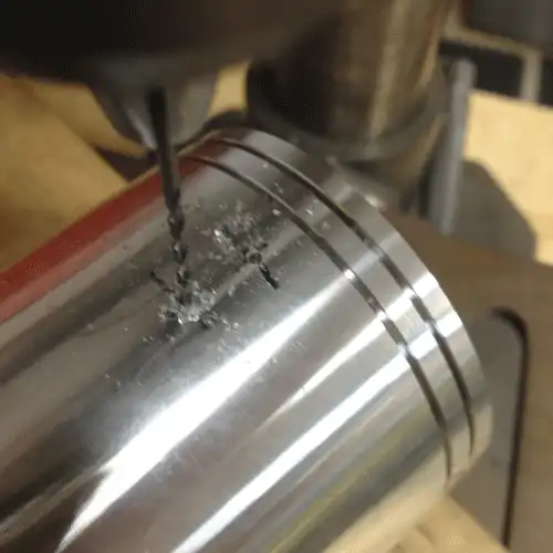
- Start 0.300” below the bottom ring groove and mark two points 0.375” apart from each other. Make sure the points are centered horizontally between the two lines you traced.
- Drill two holes 0.060” - 0.090” in diameter (1/16” or 5/64” drill bit) on your marked points (one hole on each point).
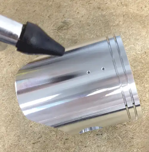
- Remove all burrs from drilling the lubrication holes. On the inside of the piston, lightly sand with 400-600 grit sand paper. On the outside of the piston, use a ¼” drill bit and twirl it between your fingers over the holes you drilled to break away any edges and imperfections.
- Wash the cylinder and piston with soap and water, and use compressed air to remove any water and debris.
- Wipe the cylinder wall with light coat of oil. Whichever 2- cycle oil you normally use is fine.
- Continue your top end rebuild as normal.
Originally printed in issue #77 of Still....Keeping Track
4/19/2017 posting from POG message board
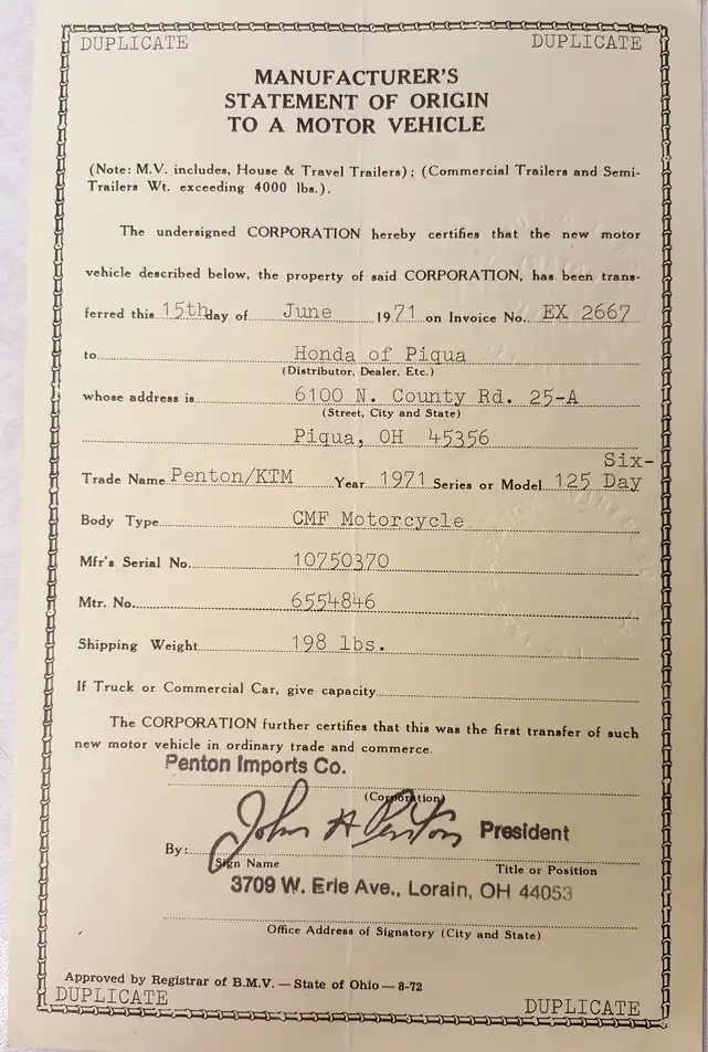
James Giddings has this Statement Of Origin that caught my eye.
The Statement Of Origin was issued to a dealer in June of '71, but according to the frame number, the bike was not built until July.
-Gary Roach (OH)
4/20/2017
Gary,
Given that the first CMF machines have a build date of June of 71, Penton Imports most likely had a few machines air shipped over as soon as they were built in June to be able to show and/or race them to build up the demand for the container loads of them to soon follow.
The date on the MSO is June 15th, a Tuesday. I can just picture Jack and the boys showing up at a big MX race on the Sunday before and kicking butt on the new CMF machines. Monday morning the dealers probably started to call Penton to place their orders.
Penton probably asked for and received pre-payment in full for the machines ordered and they then supplied the dealers with MSOs for the yet to be built machines as a guarantee of delivery. I am sure that dealers knew they could get full price for these new machines and were willing to pay up front for guaranteed quick delivery once the container arrived. Those who could not pay in advance just had to wait and take their chance at machines being available, where as payment in advance guaranteed a machine right out of the container.
Figuring the build date of July and just assigning serial numbers in order would not have been much of a stretch for KTM and John to figure out in return for cash in hand.. If by chance a certain "promised" machine ended up in Italy surely Penton could just supply the "correct" MSO when delivery took place as I am sure the dealer was just lusting over the new machine and if the original MSO was incorrect and a new one was supplied, he probably wouldn't really care.
It states on the MSO that ownership of the new motor vehicle has been transferred on June 15th and I don't think Penton would have done that without payment in full.
Just my theory…
I do know that Penton Imports was great at marketing. I can still picture John telling the dealers at Penton Dealer School how the bikes in the warehouse would be sold at the old/lower price and the ones arriving in the next container would have the new price increase…and how the more machines they bought now and took home with them the more money they would save/make…. Those dealers crammed as many new Pentons in their vans and onto trailers as they could, saving all that money. Possibly that is why Penton had dealer school in February when sales were the slowest.
-Paul Danik (PA)
4/20/2017
An astute observation,Paul! I remember going to one of those meetings with the owner of Campus Cycle in Cincinnati! Way back then!
-Oldebonz
4/20/2017
Oldebonz,
Do you remember what year you were at a Penton Dealer School or where it was held at? Please do tell of your experience if you care to. Any special memories from the event? Possibly the introduction of any new machines might pin point the year.
As far as the MSO date issue, possibly it simply may have been a typographical error, especially since it is a duplicate. It would be neat to find another from that time frame and see how it is filled out.
-Paul Danik (PA)
4/20/2017
Believe it was about 1969,the owner, Mark Schmidter set up an AMA regional(or national??) MX out at his property,MotoWest??
between Cleves and Miamitown,Ohio. Many of the top motocrossers in the country were there. We were dumbfounded by these two little teenagers on these spindly little motorcycles(Penton)we had just barely heard about,and Jeff and Jack in the 100 and 125 expert classes cleaned house!Mark was just branching out from Yamaha (just got Bultaco,in process with Husqvarna) just came naturally to pick up Penton since John did the Husqvarnas..Been almost 50 years ago,I was awestruck,remember the pep talks,forget who(maybe Doug?) we were paying a lot of attention to on transmission set up because we had some problems with a couple of the first ones.
Later we picked up Greeves,Stan Simpson past AMA Chairman of the board) and I got 380's and 250's,loving the handling,hating the 4 speed gearbox in enduros.We thought the Penton's were "too small" for us since we were big guys!I now have a 1974 100 Berkshire, pulls me just fine!
-Oldebonz
by Robert Patton
Originally printed in issue #77 of Still....Keeping Track
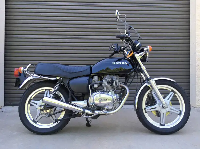
One of the many motorcycle magazines to which I subscribe did a multiple-part story on restoring a 1970 Honda CB350. Honda fans, you can follow the rebuild at www.motorcycleclassics.com.
How does the MC Honda restoration tie in with the Penton Owners Group audience?
Easy, the MC article tells of their trials and tribulations and, since I have used/modified/adapted many of their tips, I can give you an update on “did it really work” and add some school-of-hard-knocks updates.
Let’s Go To Work
In Part I, Motorcycle Classics writer Richard Backus sets the stage. He is taking a tired CB350 (purchase price $200) and his goal “is not a restoration, per se—think of it as a sympathetic rehab, bringing a motorcycle back to road worthiness.” That was Backus’ stated goal, but by the time he reached Part VI of the story you could see that the bike was a nice restoration. Backus’ articles were truly inspirational.
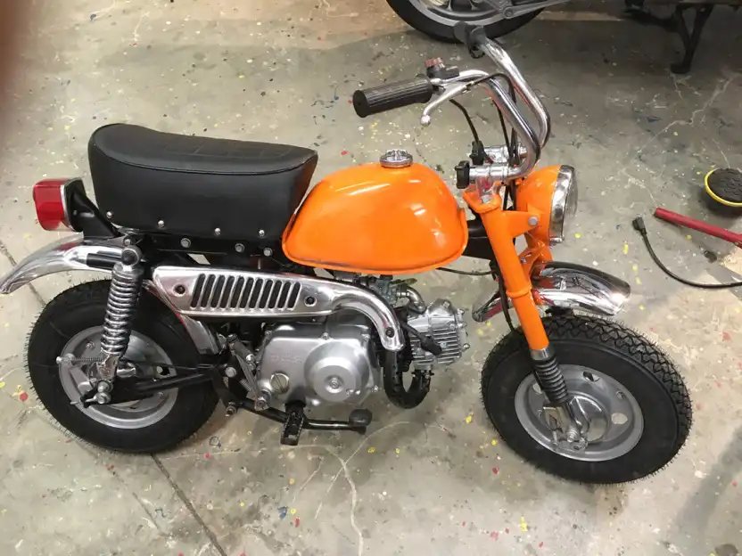
I had not read the MC article prior to starting my own restoration/rehab/refresh of the following motorcycles, all 1970s vintage: two Honda Z50s; two Honda CT70s; two Honda CT90s; a Honda CB400T; a Penton 125 and a Penton 175. However, I started the project in the same manner: Step one, does the engine run? If it doesn’t fire, does the engine have good compression?
Note to self: At a minimum on a motorcycle restoration the carburetors will have to be cleaned. So let’s get out to the shop and do some work!
Motorcycle guys, here is a point where you have to make a decision. Do you log on to eBay and purchase an aftermarket set of carburetor rebuild parts, purchase an OEM set of rebuild parts, clean your parts in a one gallon solution of “Berryman Chem-Dip” cold solvent, clean the parts with an ultrasonic cleaner (a great excuse for a shop tool), or send the carbs out for cleaning?
With varying degrees of success I’ve tried all four options. I’ll list the pros and cons of each and give you some prices to help you make a decision.
1) Carburetor rebuild kits, aftermarket versus OEM. Wow, it is impossible to help with this price comparison because prices for carb kits are all over the board. Can we agree that aftermarket parts (when available) are, typically, half as expensive as OEM (when available)? Note the use of “when available,” with any 30+ year old vehicle supply is sketchy. No worries, see “4) Send the carbs out for cleaning.”
2) Clean in cold solvent (Berryman Chem-Dip). I’ve had marginal success with this technique. Beware, as it says on the side of the container, “Don’t leave aluminum parts in the solution too long.” The solvent will loosen the grit and contamination, but it takes scrubbing to remove the dirt. (Hey, that’s what the ultrasonic machine does, right?)
But, remember, don’t leave the parts in for too long as it turns the aluminum a dark grey, crusty color. (Ask me how I know.)
After playing around with two-gallons of the cold solvent and looking at the results, I am not a fan of this technique.
3) Clean with cold solvent in an ultrasonic machine. I purchased a “shop tool” (don’t tell the wife). A Kendall Ultrasonic/Cleaner (HB36 - 6 liters) from Amazon. Price $ 399.
I really like the machine, it is great for cleaning small parts. However, even when you cut the cold solvent 25/75 with water, or you use a Purple Power-type solution you still run the risk of oxidizing the aluminum into the dark grey crusty color. (Ask me how I know.)
The machine is really good at cleaning the nuts and bolts, although for show quality results you’ll have to have the parts re-plated. For a quick rehab/refresh you can give the nuts and bolts a light spray of Rust-Oleum “Aluminum” paint to keep a re-rust situation from happening.
4) Send the carbs out for cleaning. Finally a cost-effective answer to help us start (literally) the project.
Like you, I have seen the vapor blast advertisements in magazines and was skeptical of the process and leery of the price. However, fellow Penton (motorcycle) Owners Group (POG) members recommended Dan Vitaletti at Vapor Blast Solutions (vaporblastsolutions.com) and he cleaned five wheel hubs ($90) and then three carbs and a reed block ($80) and the parts looked better than new.
Really, better than new.
Dan Vitaletti is in the process of moving to Washington state and should have his machine ready for work (it is a hobby/business) this fall (vaporblastsolutions.com). Other sources: Clean Machine Blasting (.com) in Savannah, Georgia. I sent two Honda Mini-trail 50 carbs to Richard Hinely at Clean Machine and the invoice was $30. That’s right, only $30.

by Alan Buehner
Originally printed in issue #76 of Still....Keeping Track
One of things that one has to deal with when owning a motorcycle is cleaning it. It can be a very simple chore if you are dealing with a street bike, but dirt bikes, especially “barn fresh” vintage bikes can be a frustrating challenge. Old grease and oil mixed with dirt will not dissolve. Certain types of dried up mud, especially certain types of clay, turn to concrete.
So the question comes up, what do I use and do to clean this stuff off of my bike and clean up the engine parts? We generally will experiment with trying whatever chemicals that we have in our garages. Back in the “old days” we would not think twice about using gasoline for cleaning and this was commonly used for cleaning the air filters. Today we know better than to use certain things that are hazardous to the environment and to our health. Breathing fumes and getting that stuff on our skin can pose serious health risks.
Years ago I purchased a case of citrus based cleaner in spray cans made by Stoner. It works good on removing grease and oil but requires a lot of scrubbing and brushing.
So what should we use and not use? What works and doesn't work? This came up on the POG message board and this is what the “experts” recommend.
7/17/17
Im thinking about refilling my parts washer which has not been used much at all since I bought it many years ago, mainly because Im not very happy with the weak non aggressive type of Parts cleaning fluids sold by most auto parts stores. I`m wondering if a 50/50 Pine-Sol water solution would be a good choice, since it works so well soaking and cleaning carbs. What does everyone recommend, or use in their parts washer/cleaners? Thanks for any and all input.
-Mike Winters
Mike, a long time ago, someone mentioned using diesel fuel as a parts cleaner, might work with the elec. pump as is low flash. Just a thought.
-Tom Brosius
I use the cleaning solution that Tractor Supply sells.
-Thrownchain
There seems to be some pretty good reviews on the Tractor Supply product for $39.95/5 gal, and that's not too far away for me to pick up some in the next couple of days. Thanks.
-Mike Winters
I have always used Agitene that Granger sells, it is pricy, but the best I have found. I soak Sachs engines in kerosine for a couple months before pulling them apart to loosen up all the old oil and crud inside. This makes disassembly and cleaning the inside a whole lot easier. I also wear gloves to protect my hands.
-Ron Carbaugh
7/18/17
I have Crystal Clean come out and service my washer, about $150 each time once a year. They also add my choice of nice smelling deodorant to the cleaner to make the shop smell nice. No mess, no fuss, all professional.
I use no flammable solvent (or very high flash point) to clean anything all stripper used is also green and correct PPE is used at all times when working with solvents.
I take the old solvent and filter it as best as I can then throw it in a horse trough to soak frames, wheels etc. to degrease the major gunk from them prior to cleaning and blasting.
For the bikes, I use cold water and S-100 spray. This has always worked for me.
Only glass bead is used in my cabinet to blast items. It is filtered with HEPA class filtering to keep it green and safe.
Keep this safe and practice safe work practices and all will be well.
-Kip Kern
7/19/17
Tried diesel fuel and an ultrasonic machine but did not care for the results: too messy/stinky and the diesel oil film remains long after the part is cleaned.
Have had good luck with the Purple Power stuff on nuts/bolts, but it will oxidize the aluminum parts.
-Rob Patton
7/27/17
I too have seen the results of Purple Power on aluminum bike parts, makes a new bike looks 10 years older than it really is, great on greasy engines but really caustic on shiney aluminum. At all the shops I ran, we used Safety Clean on a bi-monthly basis, just my $0.02
-Mike Gallagher
I use Pine Sol for carburetor cleaning.
I experiment all the time with degreasers and have not found anything that I really like so far.
For stripping paint I use Cistristrip (available at Lowes). It is a gel that I apply to engine cases, cylinder fins (black cylinders), fiberglass tanks (use caution, do not leave it on over night or it will bubble the fiberglass). I use a pressure washer to blast it off.
The best cleaner and degreaser that I have found so far is ZEP Industrial Purple Cleaner and Degreaser Concentrate. You can use it diluted or full concentrate, depending upon what build up you need to remove. I spray it on and use a tooth brush to work it in.
One of the things that I have used that does not work is Simple Green.
For getting rust off of metal items, such as crank shafts and any rusty steel, I use Metal Rescue (available at Home Depot). This stuff is bio-degradable and can be flushed down the drain when it has lost it's consistency. You just soak the rusty part in the solution for a couple of hours or more (depending upon how much rust is involved) and rinse the part off with water. It is also important to remove any grease or oil from any rusty parts before using Metal Rescue.
I also try and scrape off as much of the gobs of gunk and dirt before using any cleaners.
- “Chicago Jerry” Grakauskas
By Alan Buehner
Originally printed in issue #75 of Still....Keeping Track
What do you look for when you have spark, but the engine just won't start? I had a customer in Australia e-mail me about this problem with his Sachs engine last week. This was my response:
This could be 1 out of many possible problems.
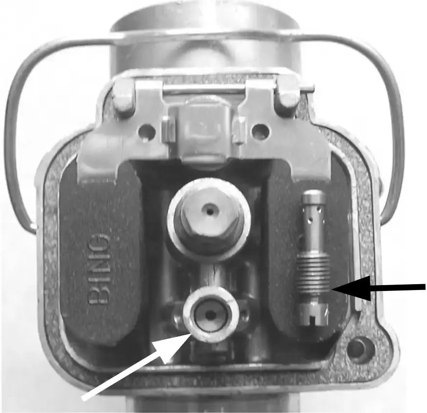
#1 - Carb - replace the missing wax (in choke chamber) with a small dab of silicone (must be flat at bottom to block small brass orifice in bottom of choke chamber). This applies to Bing 24-27mm carbs with the choke chamber on the side.
#2 - Carb - remove the idle (pilot) jet and make sure that it is not blocked up
#3 - Ignition – Weak spark is not sufficient to fire up the fuel/ air mixture. Try push starting it with the throttle closed. .
Before I installed a Power Dynamo ignition in my Jackpiner, I would have to push start it to get it going for cold engine starts.
#4 - Pipe - Make sure that the exhaust pipe is not blocked. Mice like to build nests in the pipes filling it up with bedding and shells from nuts. A blocked pipe will not allow the engine to breathe..
#5 - Carb - double check the floats in the carb. Are they level with the carb body? Are they operating the float needle correctly? Allowing gas to flow and shutting it off? Is the float needle sticking in the closed position?
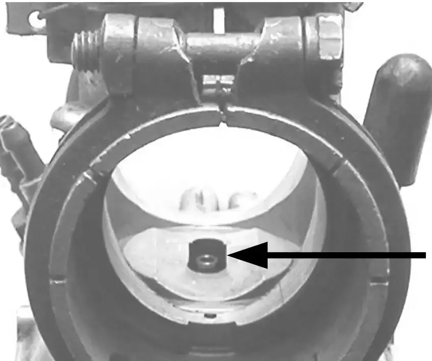
#6 - Carb - double check the position of the vaporizer (brass part that surrounds the opening of the needle jet in the mouth of the carb). If it is the style that has the half moon cut out - the cut out section must be facing towards the engine. (see photo)
#7 – Flooded engine – Crank area flooded with gas, try push starting with throttle wide open.
I ran this article past Kip Kern and these are some suggestions that he added:
#8 Carb - make sure float needle doesn't have a groove worn in it from being old. If so, replace it so it will seat properly. You may also need a new seat.
#9 Petcocks - Make sure your fuel cocks are flowing properly and the seats are not cracked or plugged.
#10 Air Box - Had one guy who left a rag in the air box and it resulted in no airflow to the carb.
I ran this past Chicago Jerry and this is what he added:
#11 Carb - check that idle jet is not blocked. Running pump gas in a fiberglass gas tank can cause blockage.
#12 Ignition – out of timing from a sheared woodruff key on a Bosch or Motoplat, or spun flywheel on a PVL or PowerDynamo.
By Alan Buehner
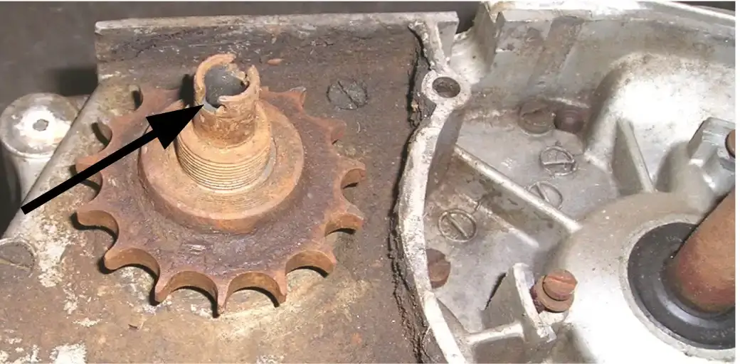
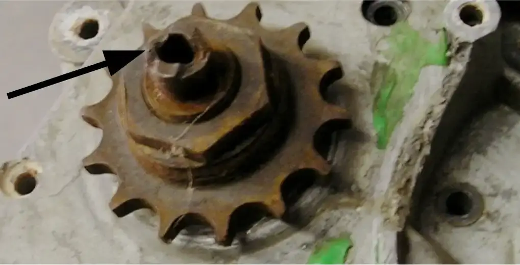
Sachs counter shaft sprocket are a taper fit to the end of the main shaft. There is no woodruff key used and the sprocket is held firmly in place by the taper fit.
The end of the main shafts are slotted to fit into the tabs of the brass spiral VDO drive gear inside the ignition case (see photo A). Failure to install a protective cap on the end of the main shaft when using a puller to remove the sprocket will result in the slot splitting and breaking off. (see photo B).
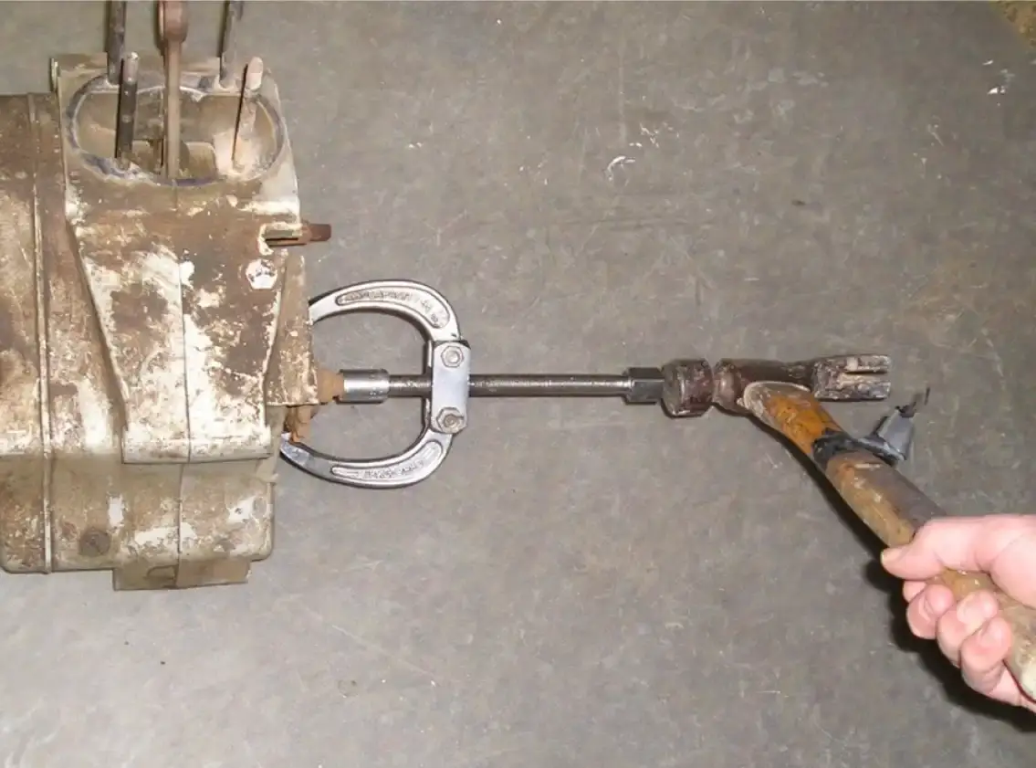
Original factory pullers (Sachs part no. 0276-011-105) and the protective cap (Sachs part no. 0676-012-200) are difficult to find but are not required to remove the sprocket. You can use any heavy duty gear puller as long as it will fit under the teeth of the sprocket.
You can use a 13mm socket as a protective cap. Just place it over the end of the main shaft (as shown in photo C).
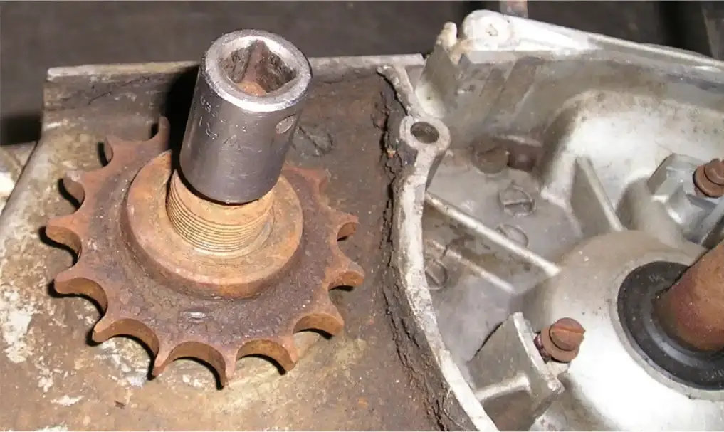
If the end of the puller is a smaller diameter than the O.D. of the 13mm socket, then it would be best to place a thick washer between the socket and the puller to prevent the puller from getting impaled into the socket. Photo D shows a puller in position over a 13mm socket.
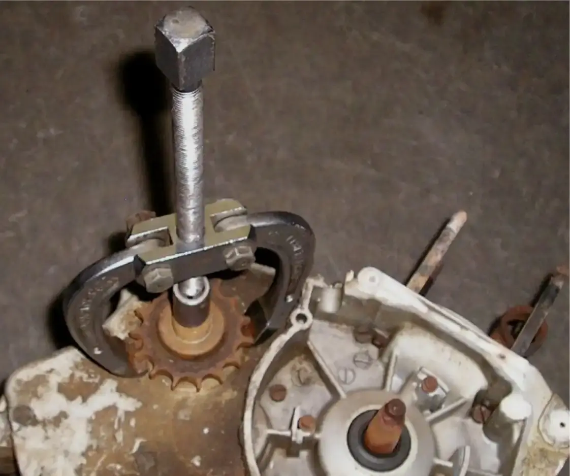
Because the taper fit is so tight, do not expect the sprocket to come off easily. You will be tightening down on the puller to the point where you will swear the puller is going to break which is why you need to use a drop forged puller. A cheap steel puller will only bend.
When you get to the point that the puller becomes difficult to turn, stand to the side of the puller and give the crank end of the puller a good strong wack with a hammer (see photo E). The sprocket will literally fly off the end of the main shaft. Heating only the sprocket will help the sprocket to expand and should make it easier to remove.
from the POG Message Board
After seeing this posting (made on 09/07/2013) on the POG message board (under Penton Racing Talk), and seeing the response to it, I decided to use it for this issue's Tech Tips to share it with our members who do not use computers or use the internet. This is good information as to what problems you can run into if you use big hammers and not the proper pullers and tools when working on engines. Also when buying that non-running bike or engine, this is one of the problems you can encounter when someone else did not use the proper tools. Thanks to the POG members for sharing this information.
Alan Buehner
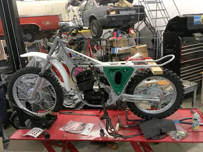
I have two penton 125s and one of them, my race bike, I recently put a new forged Wiesco piston in it to replace the Mahle that was there.
I noticed that the other 125, though low in cylinder compression (since it is still in it's standard bore), is a much smoother sounding motor than the other with the new piston in it. To describe the motor with the new Wiesco piston; it has these cyclical or eccentric motion vibrations in it. Hum……??
POSSIBLE SOLUTION: If you look on page 41 of the Sachs powered workshop manuals provided by Beuhner's Supply, you will note the 4 steps in "Balancing The Crank". On the first step, you will see that the piston is included when determining the weight of the assembly. Therefore, if the Wiesco piston is lighter, as it feels, the assembly is no longer balanced, thus a source of vibration when the motor is running despite other good functioning parts of the motor….
QUESTION: Those of you who restore motors, do you re-balance the crank assemblies if another brand piston is installed and the weight is different???
Let us know your comments.
Peter Klinck
After reading page 41 in the Sachs manual, this is a simple & practical way to balance the crank shaft. This is also be a very time consuming process. I am sure the engine may run slightly smoother with this done but usually the different piston weighs only grams apart.
When rebuilding\restoring an engine I am mostly concerned with the runout between the 2 crank halves and not the "balance" of the crankshaft. The closer to 0 runout the less vibration the engine will have. This is usually the main source of engine vibration.
Jerry Birky
You can not really "balance" a single pin crankshaft in the literal sense. A Boxer opposed twin pin crank is the easiest because the reciprocating mass (rods/piston) completely offset and counterbalance each other and that allows you to "Zero" balance the rotating mass (crank wheels/snout). The single pin crank (whether a single cylinder or a single pin twin like a Harley) can not have the rotating mass of the crank zero balanced because the reciprocating mass is constantly in a state of imbalance, not being offset by an equal and opposite mass. What you can do is "tune" the single pin assembly so that you get the least amount of harmonics (vibration) in the most often used RPM range. That is why a Harley engine vibrates so much more at idle than at highway speed, the crank is balanced to run smoothest at that speed. In the Penton/Sachs example, the small difference in piston weights will have minimal effect and what Jerry Birky mentioned, runout of the two halves, is the most important thing to fine tune.
Brian Kirby
Peter,
You have hit on a topic that is quite interesting, please excuse my long reply..
"Back in the day", the local Penton dealership initially was owned by Kupec Cycle owned by Fran Kupec, Fran eventually sold the dealership and it was picked up by an engine building and machine shop, J & D Engineering in Valencia, PA. The reason they picked up the dealership was to supply their own needs for motorcycles, as they were all weekend riders, as well as to sell some machines, like many single brand shops of that era. What they didn't realize at the time is that I went along with the sale….
The guys at J & D did tons of balancing of cranks for every sort of engine. The guy who actually did the cranks was Dunk Pacdozi, if any of you were into dirt late model racing "back in the day" you probably remember the team of Dunk Pacdozi and Bob Wearing Sr., their accomplishments are legendary in the tri-state area. The other specialty at the shop was cylinder head modification, they really understood the connection between cylinder head flow, proper engine balancing, compression, etc, etc, to get maximum engine performance along with durability. The link below will take you to a very nice write up on Bob wearing Sr and Dunk Pacdozi.
http://wearingmotorsports.tripod.com/id1_12.html
It didn't take long for these guys to turn their talents to my Sachs powered Penton, just for the enjoyment of doing it, as well as a way to promote the shop as a Penton Dealership. Their opinion of the balance job that was done on the Sachs engine from the factory was not very complimentary.
Turn the clock forward a few years to the ISDT Qualifiers in Oregon, between the Trask event and Bad Rock, we parked the Cycleliner out in the boonies along a little used road to finish prepping our machines and sort of kick back for the day. Dane and I were working side by side finishing minor details on our Pentons, soon we were both done and we fired our bikes up for a few "test runs". Well, boys will be boys, and soon we were lining them up for a blast down the road, Dane was on a 100 and I was on a 125, but Dane knew how to make a 100 run and knew he should give a "normal" 125 Penton a run for it's money, he was surprised at how my 125 consistently pulled away from him. I let Dane ride the bike and soon he had lots of questions.
My engine was worked over, including some very nice port work and a little extra compression, but the thing that intrigued Dane , and very shortly afterward John and Ted Penton, was the balancing of the crank. After some calls and information was exchanged between the folks at Penton and the guys at J & D, along with some inquires from Penton to the folks at Sachs, John hand carried one of the balanced cranks from J & D back to the factory so that they could see the difference for themselves. Those engines with the balanced crank just seemed to rev out farther, and were so smooth it was incredible. If I remember right, the balancing removed some mass that allowed for some quicker revs as well.
In 1973 we did my ISDT engine ourselves, and I have always felt is was as good, if not better than the "D" engine that came in my bike from the factory in 1974. Interestingly enough, at the ISDTRR a few weeks back, Jack put me on his Carl Cranke built 250 GS 6 on Sunday, before I rode the bike I figured I might have my hands full starting the bike and keeping it running at a leisurely pace, man was I wrong…. Just jab the kicker and it lit right up, and pick just about any gear and it would cruise along, it could almost fool you as to the power it had until you put it thru it's paces, but it was very usable power…not just a big hit that would bring on wheel spin, it reminded me of how my Sachs engines ran many years ago….smooth and strong.
Sorry to ramble, google dynamic balancing of crankshafts for some good reading, and even watch them do some on youtube, and if you get someone to dynamic balance that Sachs crank I will be curious to see what you think. Keep talking to shops about what you want to do until you find one that is experienced in dynamic balancing of single cylinder cranks, you will know the right guy when you find him.
I would also like to say that I personally am not an expert on these matters as far as doing the work and being able to provide details of the operations, but I was very fortunate to have been the recipient of the efforts of these very talented and ingenious folks and to whom I will always be deeply indebted…I just loved to ride, and they just loved to tinker…
Paul DanikI finally found out the problem and subject issue associated with single cylinder crank vibration on my 1973 penton 125 with a Sachs B motor.
1.) I started to disassemble the motor. I was just about to separate the case halves, tilted the bottom end on it's side and heard a sound… I grabbed onto the crank spindle and found lots of lateral play, say .030 approx. although there was all new bearings in the motor on a recent rebuild, this was too loose and was a cause of the vibration. Lucky the bearings were new and so did not have enough movement up and down and thus did not ruin my new MZB ignition. THIS LOOSENESS MAY HAVE BEEN CAUSED BY POINT 2 BELOW.
2.) I then broke the cases down and took out the crank assembly. A couple of weeks later, I took the crank assembly over to a garage and put the crank on a metal lathe. In fact, he had 2 lathes so we began to test and check the crank spindle straightness or run out, etc. The following results were;
aa) Mag side spindle (from the more true lathe)
- measured on end of crank next to threads: .0085 thousands out of round
- mes. just on the inside of the flywheel: .007 thousands out
- mes. on the inner crank bearing race: .004 thousands out of round
bb) Clutch gear side
- .00050 thousands out. this was ok
Conclusions: I think the crank spindle on the mag side has or had been bent. SO I believe it is now not of worth?
Question: Is it not a basic bench test when a new rod assembly is replaced to check on a simple lathe whether the crank assembly is straight? I suspect so….
Let me know of any comments on this subject.
Peter Klinck
I've seen a great deal of crankshaft spindles ruined by improper use of a large hammer when pulling a flywheel, even with the correct tool without the spindle nut installed during the process. Without the nut installed loosely, the shaft tends to deform and bend. The problem with Penton and KTM pullers, is that there is no room for the nut to remain in place.
Michael R. Winter
My three cents worth on the subject! Typically each crank half has two center drilled blind holes, one on the shaft end and one on the flywheel end. Very frequently the one on the shaft ends are damaged by puller tools, hammers!, … If the crank is being trued up by holding and spinning the crank on these end holes between centers on a lathe or truing stand, and one or both are damaged, the run out readings will be false, leading to a crooked crankshaft rebuild. When the crankshaft I am working on is pressed apart, I always check each half between centers for trueness, which will uncover damaged center drilled holes. I can't say I have ever found the actual shaft portion to be bent, it is almost always a damaged end hole giving false readings. I have developed a technique using an eight or ten flute, 60 degree carbide counter sinking tool in a drill press, and holding the crank half in my hand to "fudge" the end hole back straight and centered, and yes, I said by holding in my hands!! Sometimes it takes many, many tries back and forth between the drill press and the truing stand to get it right: 30+ minutes once!, but the results are worth it, and the only way to fix these old dirt bike parts.
The first Penton 125 6B motor I built, with a oem piston vibrated like a washing machine, so bad I asked a racer from the day, and he commented that they were like that. The second motor I built used a much lighter, modern Wiseco piston, and the engine was much smoother. Since single cylinder cranks can't be 100% balanced, engine with heavier cranks are smoother than those with light cranks, 6B being the lightest Sachs crank! The modern made forged Wiseco pistons from Al Buehner are much lighter than the oem Mahle pistons. Hope this is of some use to Poggers!
JP Morgen