

Carl Cranke 250 Porting
by Alan Buehner
Originally printed in the 2000 issue #8 of Still....Keeping Track
In January, I contacted Greg Johnson of West Virginia who faxed me a copy of a Penton West Dealer Service Bulletin (no. 7) issued by Carl Cranke who was the Service Manager at the time. In my conversation with Carl at Sears Point in April, I asked him if his porting is just for enduro riding. His response was that it was good for any kind of riding. In talking to people who have ridden one of Carl's bikes, their response was that the power was available anywhere on the throttle and that it was controllable and predictable. The following is his porting specs:
- Set the deck height (distance from top of cylinder to top of the top ring) at 1.0 mm or .040 inches.
- Install a degree wheel and find top dead center
- Rotate engine clockwise 86 degrees and scribe a line above the exhaust port.
- Rotate engine 114 degrees A.T.D.C. and scribe a line above second set of transfer ports.
- Rotate engine 116 degrees A.T.D.C. and scribe a line above the front transfer and rear boost ports.
- Rotate engine 80 degrees A.T.D.C. and scribe a line on the piston along the bottom of the inlet port.
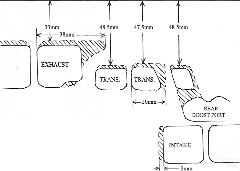
- Raise and widen all ports to the scribe lines according to the diagram supplied. (NOTE: be sure to radius exhaust port to top edge).
- Match and blend transfer port passages at bottom of cylinder to match crank cases.
- Match inlet manifold to inlet port. (Use gasket as a guide).
- Use an expansion chamber with the dimensions supplied.
- For tight race tracks, use an internal rotor ignition (timing 2.8mm B.T.D.C.)
- Carburation will remain basically the same, but will vary according to local track conditions.
- Port timing in degrees of total duration:
| Standard Cylinder | Modified Cylinder | |
| Inlet Port | 160 degree | 160 degree |
| Second Transfers | 124-125 degree | 132 degree |
| First Transfer and Boost Port | 121-122 degree | 128 degree |
| Exhaust Port | 184-185 degree | 188-190 degree |
TOP OF CYLINDER
250 EXPANSION CHAMBER
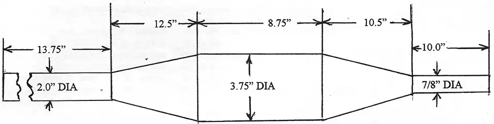
measured through center line of pipe.