KTM Motor Cranks
by Bobby Lucas
Originally printed in 2000 issue #7of Still….Keeping Track
The following information is for the type 51 (125), 52 (175), 54 (250), and 55 (400) motors. Special care should be taken to clean the motor thoroughly of any dirt and grease before attempting to pull it apart.
The KTM powered Penton motorcycles are without doubt one of the most reliable if not the most reliable 2 stroke engines of all time. Restoration of these engines is going to be either very easy or very difficult based on the condition of the project motor.
Magnesium is a product that is very light and very strong, however, once exposed to the outside elements for a long period of time, moisture can cause corrosion inside your engine crank housing. Tolerances on KTMs are so close that many engines that I start to rebuild are locked up and the crank and piston are frozen in the cylinder and cases. If I come across one with a frozen crank and or piston, this is what I do: Remove the clutch case cover. The KTM engines have a crank case drain plug which I use along with a parts washer to flush out the crankcase. Soak the engine and use a socket on the pinion nut to rotate the crank. Usually only a small amount of movement can be achieved. Work slowly and you may free the crank. Your piston may also be stuck in the cylinder. My trick here is to remove the head then the case studs. Rotate the cylinder in a clockwise counterclockwise motion, again easy does it and with ti me you can usually work the piston free from the cylinder. (If the piston is rusted solid to the cylinder, split the cases and remove the crank assembly with the piston still in the cylinder. The piston can then be removed with a press.)
Follow the Penton Service Manual for all the proper steps in your engine overhaul. Care should always be taken when disassembling an engine and use of proper techniques and special tools should be the standard to follow.
Special tools are required to work on this engine type and using other tools and methods should only be done by someone who has lots of experience or spare parts to replace the ones you may destroy.
A 40 ton press is required to work on the crank and special holders for clutch basket and pinion gears are needed in disassembly and reassembly.
One tool that is required is the bearing puller for the crank bearings M20 and M25 and the bearing extractor for the pinion shaft bearing.
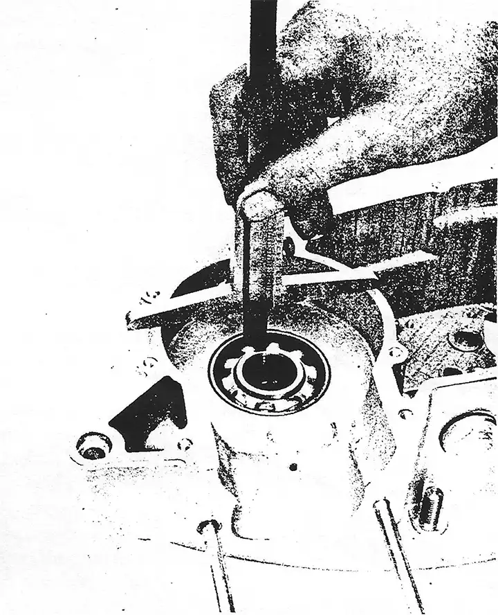
Split the cases once you have freed the crank. You may split the cases with the crank still frozen, but be very careful. One item which hinders case splitting is the driving shaft. It has a spacer which is between the sprocket and bearing. On most occasions tapping on the shaft will free the spacer and splitting the cases is much easier.
Once your engine is apart, check all case castings in the crank areas for corrosion and the two small port holes. These two holes are for lubricating the crank bearings. Make sure that they are not blocked with sludge or corrosion.
If your scope of work is not a total rebuild of your engine and only the crank demands work, there is no need to proceed any further into the transmission or clutch.
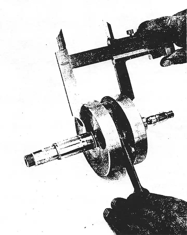
Measure your crank width before pressing it apart. In the case of a 400, measure the weights then remove them. Measure the crank journals and record all measurements. This is your target when reassembled.
Follow the directions in the Penton manual for KW axial play and record this information also. For correct dimensions always measure several times to insure accuracy.
Note: This only applies to the crankshaft 400 cc starting with motor no. 2809.
Starting with the above mentioned motor number, a crankshaft is installed in the 400 cc motor to which two damper rings are fastened by screwing. In case of such motors with this crankshaft, the motor casing is altered, too.
For spare part purposes, all 400 cc crankshafts are delivered with the threaded holes for damper rings (Spare Part No. 55.30.018.001).
Such crankshaft can be installed as usual in the old casings. For motors starting with motor no. 2809 this crankshaft has to be completed with the damper rings (Spare Part No. 55.30.032.000) and the respective countersunk screws M6x12 DIN 7971.
It is however necessary to glue the damper rings with OMNIFIT Type green 150 M and the countersunk screws with OMNIFIT Type red 80 M. It is also possible to apply the corresponding equivalent products of LOCTITE.
After the gluing process the crankshaft needs a resting time of about 24 hours enabling the adhesive to harden.
The ready crankshaft may be ordered under spare part number 55.30.018.101.
From Penton Manual
Crankcase pre-assembly
Remarks: As previously mentioned the ball race rings and ball cages of the main bearings must under no circumstances be mixed together.
Main bearings should only be renewed as sets, never singly.
Measuring of KW axial play
If you renew the crankcase or the main bearings, the axial play of the crankshaft is to be measured. This must also be done if only removing the outer ring from the casing.
Place the engine casing halves with the inside facing upwards and place the ball cages with inner race rings in appropriate outer race rings in the casing. With the depth gauge, measure the distance from the casing joint face to the bearing inner race surface.
Make a note of measurement results and measure the second crankcase half. Add together both measurements and add to this 0.2 mm for the gasket.
Measure the crankshaft at the bearing contact surfaces and also make a note of those measurements.
THE axial play, through different thickness of compensating shims between the crank web and the bearing inner race rings should be so arranged that there remains an axial play of about 0.03 - 0.05 mm.
Example:
| Left crankcase half | 27.48 mm | (1.0818) |
| Right crankcase half | +27.45 mm | (1.0807) |
| Gasket | +0.20 mm | (.0078) |
| Measurement in Crankcase | 55.13 mm | (2.1703) |
| Measurement of Crankshaft | -54.50 mm | (2.1456) |
| Existing axial play | 0.63 mm | (.0247) |
| Permitted axial play | -0.03 mm | (.0011) |
| Equalizing difference | 0.60 mm | (.0236) |
This difference on both sides of the crankshaft is adjusted by the compensating shims. If the axial play cannot be corrected with the same number (thickness) of compensating shims on both sides, then the larger number should be fitted on the clutch side. Press ball cages from the inner rings.
Before forcing on the inner race rings, in each case there is to be placed an intermediate plate between both crank webs. This intermediate plate must be large enough for support of both sides and thus the crank shaft clearly rests upon it (press on inner rings with inscription outside).
Never tighten the crankshaft with a crank shaft pin or on the frame in the vice and try to hit the bearing inner rings. In such a case the crank webs are squeezed together and the connecting rod bearing is damaged which means the crankshaft cannot be used. After pressing on the inner rings fit the ball cage on the crankshaft.
Fix left half casing in the clamping frame; oil the retaining rings and introduce the crankshaft. Fit the gasket and fix the right half casing with screws. Rotate the crankshaft. Check with dial gauge for lateral wobble at crankshaft ends. This must not exceed 0.05 mm on the driving as well as the magneto side. Measure the axial clearance of the crankshaft, holding a dial gauge against a crankshaft end. By pushing the crankshaft backwards and forwards several times it can be ascertained that it is free. If the axial play does not lie between 0.03 mm and 0.05 mm then the crankshaft must be dismantled and an inner ring is taken out by means of the inner ring extractor. Add or take away corresponding compensating washers.