

Sachs Clutch Assemblies
by Alan Buehner
The Sachs Clutch assemblies are very dependable and almost never wear out. However, there are some problems that are now showing up after 40+ years.
One of the most common problems you can expect if the engine has been sitting for a long time of nonuse is stuck clutch plates. The plates can be broken loose if they were sitting for only a few weeks of nonuse by starting the engine up in neutral, pulling the clutch lever in and putting it into 1st gear. After a couple attempts of the engine stalling out they should break loose and you will be good to go.
If the engine was sitting unused for years, the steel and fiber plates will be bonded together and the only way to loosen them up is to disassemble the clutch and pry the plates apart.
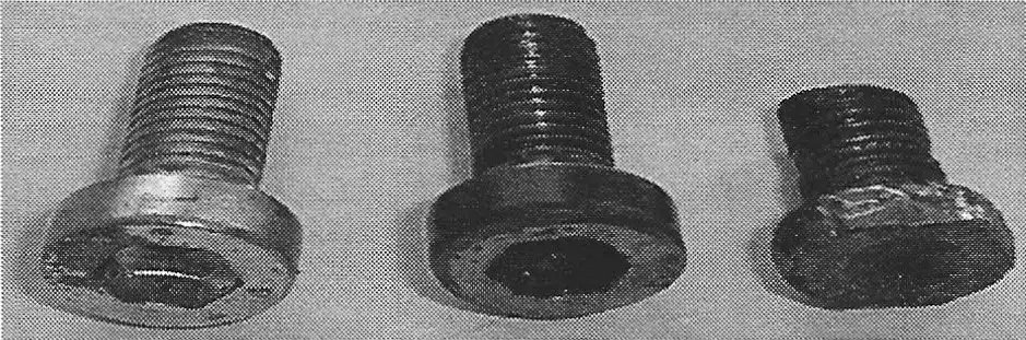
The Sachs clutch assemblies are very easy to remove from the engine. All you have to do is remove the pressure plate and then the snap ring. It can get difficult to disassemble the clutch if the Allen screw heads were worn down (see photo A). The locking nuts have to be removed first. The screws were coated with a locktite TM material and if you cannot get an Allen wrench to grip into the screw head you will have to use a pair of dykes to bite into the sides of the head to tum them. I would recommend using a dremmel tool with a cutting wheel to cut off the exposed bottom of the screw (as was done to the screw on the right). If the heads of the screws are worn, replace them with new screws - part #2740-024-002.
Once the screws have been removed you can remove the basket, the springs, and the clutch plate stack. Using a small regular screw driver, carefully pry all the plates apart. The facings on the plates will most likely all be rusty. The fiber plates can be cleaned up with steel wool. These plates are almost indestructible and only need to be replaced if chuncks of the corking came out of them when prying the plates apart.
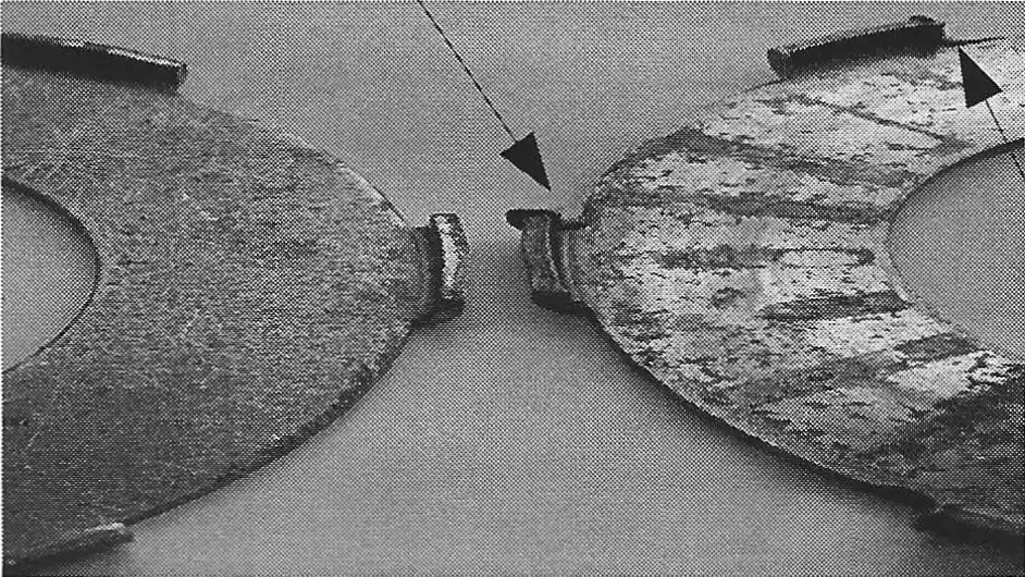
The steel plates can also be cleaned up with steel wool, but take a close look at the little tabs that stick out of the clutch basket. If they are smashed up ( as shown in photo B), then they should be replaced with part #0259-109- 000.
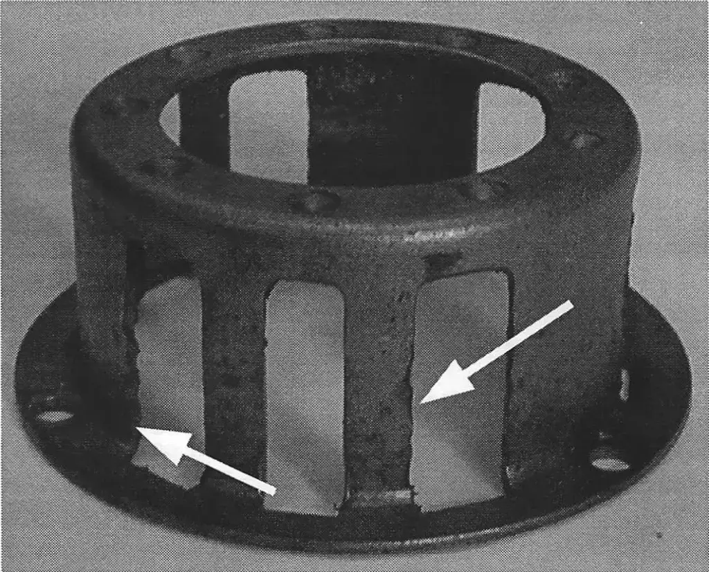
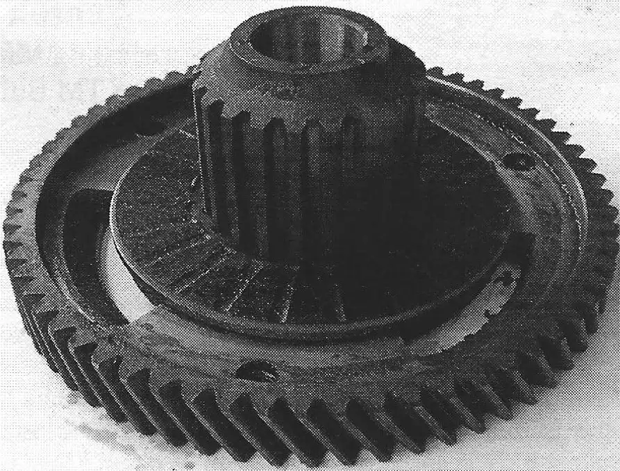
Take a close look at the clutch basket (photo C). There should be some wear, called saw toothing, where the tabs on the steel plates hit the sides. These edges can be filed down to prevent the plates from getting hung up. If the saw toothing is severe, you will need to replace the basket. Filing down the edges will create a gap and will cause more saw toothing, allowing the tabs on the steel plates more movement to bang against the basket, and wear faster, especially if the bike is ridden very hard.
NOTE: there are 2 sizes of baskets. Part #0658-002- 000 measures 40mm high and was used on all the SA engines. This basket uses springs that measure 21mm long-part #0239-015-000. The 6 speed engines came with an improved basket that measures 41.5mm high Part #0658-002-100. This higher basket requires a longer spring that is 22.3mm in length-part #0639-106-000.
The pressure plate (photo D) is another item to be looked at. Check the edges of the fingers that insert into the layshaft wheel. File off any build up on the inside and outside surfaces.
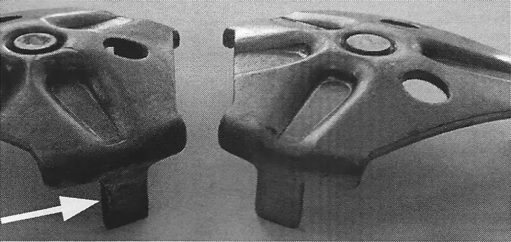
Check the center grommet for excessive wear. If the adjusting screw on the cam cup is set so that it is touching or applying pressure to the grommet, it will cause wear to the grommet. If the grommet is worn out, then the pressure plate will need to be replaced with part #0684-002-000.
These pressure plates are becoming scarce with only a few NOS ones available. Used ones can be used if they are not worn out.
Before attempting to reassemble the clutch plates to the layshaft wheel, take a close look at the bushing (photo E) in the center. See if it has any visible wear. Put the wheel onto the layshaft and see if there is any sloppy movement of the wheel. It should be a fairly snug fit. If not, replace the center bushing with a new one - part #0632-113-100. It is a press fit which means that you will need to heat up the layshaft wheel before pressing out the old bushing and when pressing in the new bushing.
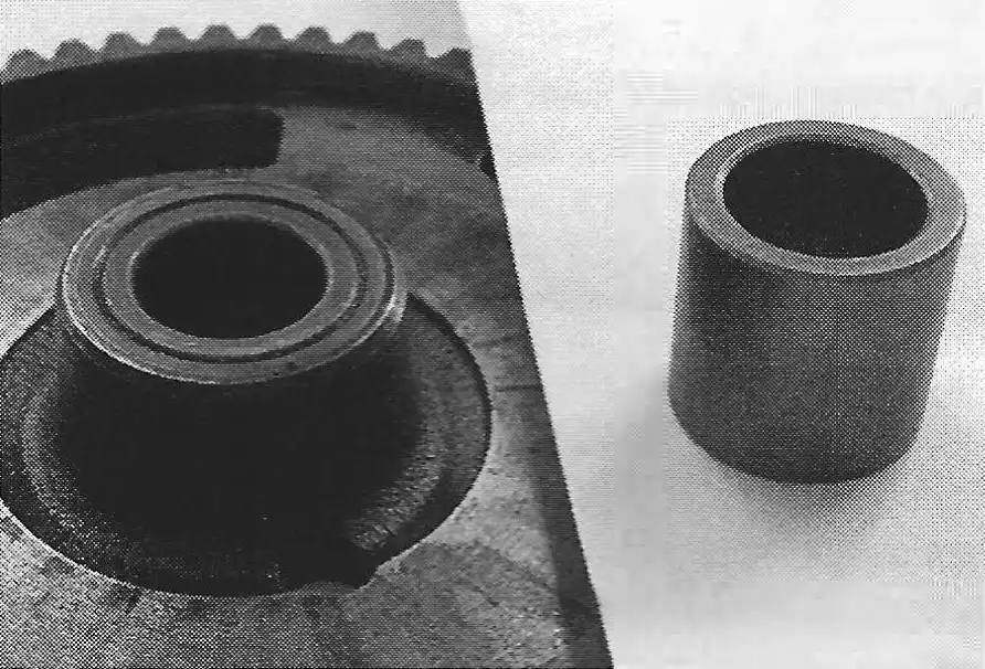
NOTE: many of the early layshaft wheel came with steel bushings. These were replaced with the brass bushing.
When installing the clutch plates, you must use a special tool (photo F) to line them up otherwise you will not be able to slide the clutch assembly back onto the layshaft. The special tool for this is the clutch hub - part #0658-001-000. Place the clutch hub tool on the layshaft wheel (as shown in photo E ) and then start stacking up the plates (a fiber plate goes on first), the springs, and the basket. After tightening up the screws and installing the locking nuts, you can then remove the tool.
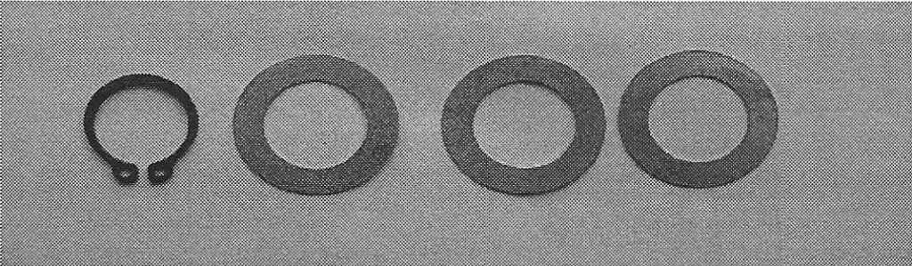
When reinstalling the clutch assembly on the engine, make sure that you install a shim washer before installing the snap ring (see photo G). There are 4 thicknesses of this washer - part #0246-015-000 is 0.3mm; 0246-015-001 is 0.5mm; #0246-015-002 is 1.0mm; and #0246-015-003 is 0.15mm. Use the proper shim to give an axial play of 0.0039 in (0.1mm) between the clutch layshaft wheel and the snap ring. If the snap ring is worn thin or has a loose fit, replace it with part #0245-020-005.
Install the pressure plate onto the layshaft wheel. Install the clutch case cover after applying a thin film of grease to the mating surfaces of the gasket and cases. If you are installing a new gasket, soak it in warm water to loosen it up. The wet gasket will also stick better to the grease coated cases and stay in place when inserting and tightening up the case screws.
After the clutch case is installed, turn the adjusting screw in the cam cup so that the screw is barely touching the pressure plate.
NOTE: this screw will cause excess wear to the center bushing of the pressure plate if it is applying too much constant pressure to it.