How to set up a Winning Penton (Part 2)
Chassis and Suspension
by Kent Knudson
Originally printed in the 2002 issue #16 of Still….Keeping Track
The following outlines the chassis and suspension components/ modifications used to build the Pentons that Kevin Brown and Gary Roach rode to their AHRMA National Championships. I would like to thank Larry Smith of Precise Welding, Jeff Reid and Joey Israel of Ohlins USA, Barry Higgins of H & H KTM and, of course, Kevin Brown and Gary Roach for their input and assistance.
First, I would like to say that we have tried very hard to retain the original components and overall appearance of the Penton motorcycle. Because the Penton already possesses an excellent design and top shelf components, virtually all of our modifications were made for the sake of greater strength and reliability. No consideration was given to weight savings due to the expense and potential for failure. If you want to reduce weight, it's usually least expensive to start with the vintage rider!
FRAME - I start with a late 1974 style frame and swingarm, which is the strongest AHRMA legal setup possible. First, strip the motorcycle down to the bare frame and check for cracks and bends. Then install the engine, pipe, and airbox, and closely inspect their fit. It is very important that all of the mounts for these items line up correctly and are not stressed! If a mount or bracket is not quite right, cut it off and set it up in the correct location.
Next, I take the frame/engine/pipe/airbox assembly to the welder. Any important frame work should be done with a TIG welder and the appropriate rod for the chrome-moly frame. First, fix the obvious cracks and bends and weld the aforementioned mounts or brackets back on. Then you can begin reinforcing the weak parts of the frame: the steering stem gussets, the breather backbone, the coil mount, and all of the other mounting tabs and brackets.
The steering stem gussets are lightly welded where they attach to the frame and can flex and bend. Tie them into the frame better with additional welds (see photo 1). The steering stem itself has held up very well for us, although by early 1975 the factory was reinforcing this area by adding a strap around the lower bearing race and welding it to the frame gussets. We use the stock ball bearing and race setup and keep them adjusted fairly tight.
The breather backbone is, in part, designed to hold the top of the steering stem in place. When landing from a jump, the forks transfer a tremendous amount of force to the steering stem. This force tries to pull the bottom of the steering stem forward and, when it can't, it tries to push the top of the steering stem back. Ultimately, this force is transferred down the length of the backbone and into the frame. Unfortunately, the rear of the backbone stamping is bent 90 degrees and extends horizontally to the left and right to attach to the frame. As a result, the backbone can actually collapse this horizontal section (the area where the rear loop for the tank strap is located) instead of transferring the force to the frame (yes, I threw that frame away!). We remedied this problem by adding triangular gussets that tie the backbone directly to the frame (see photo 1).
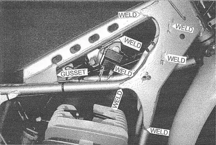
The coil mount can crack and eventually break where it makes a 90 degree bend to attach to the frame. As long as you have the frame at the welder's you might as well have him run a bead over this area (see photo 1).
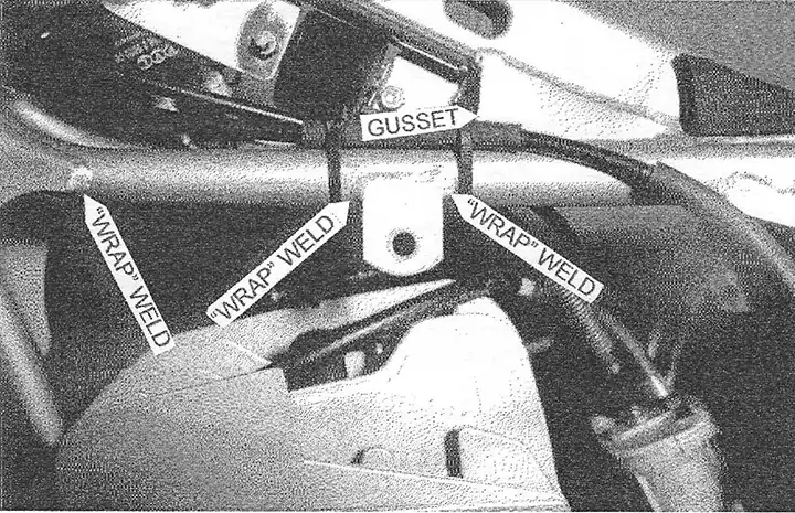
Many of the other miscellaneous mounts and brackets on the frame are prone to breakage because they are attached to the frame with a weld· on just one edge. This allows a "hinge" effect that can, . over time, fatigue the weld to the point of breakage. We "wrap" the welds around the sides of the bracket to eliminate the "hinge" effect (see photo 2).
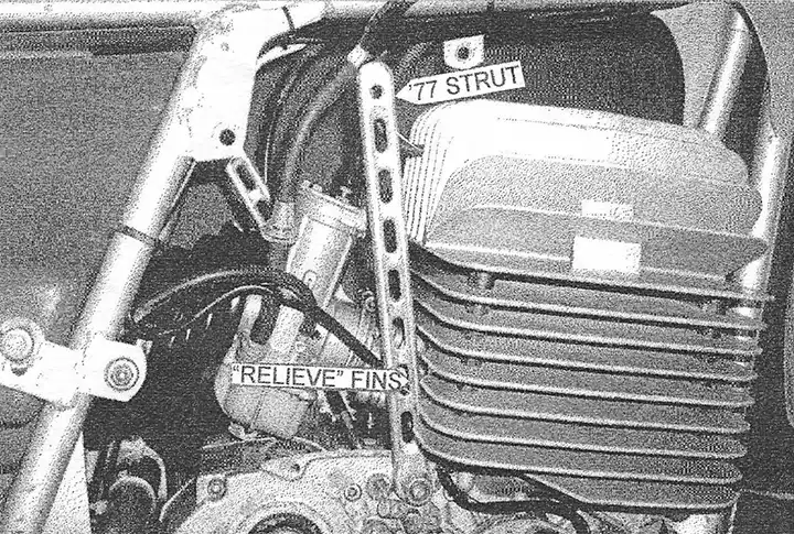
I also highly recommend using the struts that tie the engine to the frame, as they triangulate what is otherwise a square area surrounding the engine. Unfortunately, these struts make carb work very difficult. By using less bulky '77 right side struts and relieving the fins on the back of the cylinder, I was able to get the struts to rotate enough to allow adequate access to the carb (see photo 3).
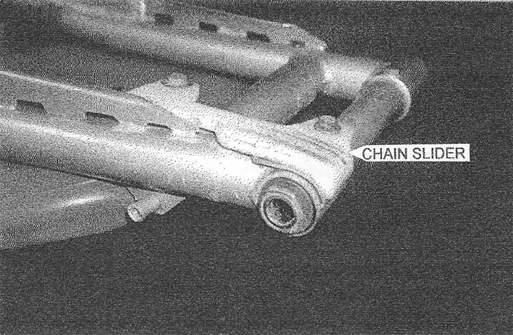
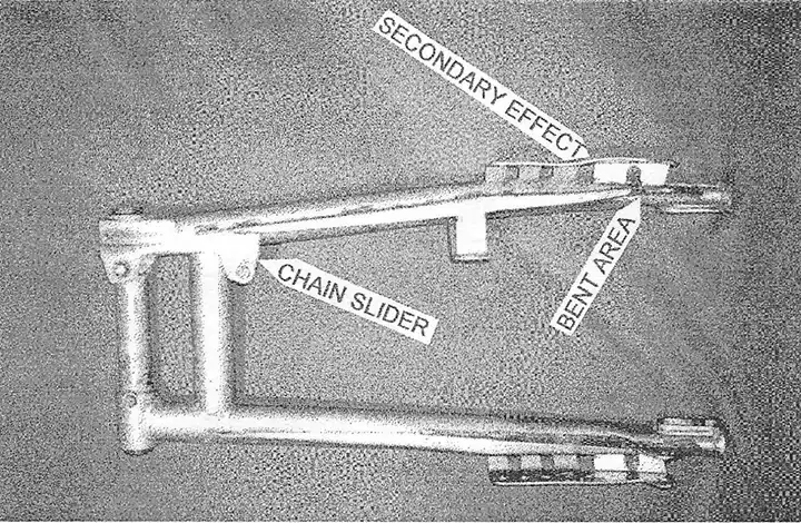
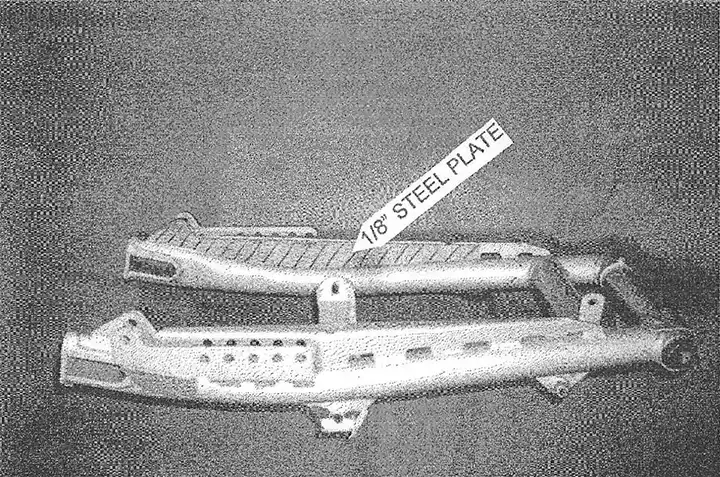
SWINGARM - The swingarm will bend fairly easily when the rear suspension is bottomed and, even with the proper shock setup, bottoming will occur. After bending several swingarms beyond repair (see photo 4), we decided to make some modifications to improve their durability. First, we cut out 1/8" steel plates and weld them into the back side of the factory gusset (see photo 5). Then, we make a chain slider out of 1/4" Teflon (see photo 6). Then, we use a jigsaw and a heat gun to fabricate the new Teflon slider. Attach the new slider using the oil filler bolt on the front and a small bracket to connect the rear to the back of the chain guide mount.
PAINT - First, I have the frame and swingarm sandblasted with fine "Black Beauty", a media derived from coal slag. Then the parts are primed with a urethane primer to fill minor imperfections and promote adhesion of the top coat. Finally, the parts are painted with "Martin Senour Tee/ One Stage Acrylic Urethane", which is extremely durable. I chose this system over powder coating because I can easily touch up areas that get worn or welded throughout the race season.
FORKS - The stock 35mm Ceriani's are excellent forks and require very little work to be race ready. We use stock internals with heavy springs from Barry Higgins of H & H KTM (770) 920-1371. The springs should have 10-20mm of preload. The fork caps will provide some of the preload and the rest can be achieved with washers for spacers. Use 15 or 20 weight fork oil (depending on your weight and riding style) filled to 6-1/4" from the top with the forks compressed and springs removed. Finally, disassemble your fork caps and make sure the check ball and spring are in good condition. I should also mention that we have used "Franks" replacement fork tubes in the past and, although the fit and finish was excellent, they bent under the extreme stresses of MX use. On the other hand, I wouldn't hesitate to use them for a show or play bike.
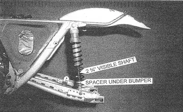
SHOCKS - We use "Ohlins Classic MX" shocks because they offer the highest quality, most advanced valving system on the market. Although the stock shocks for this frame were 13.5" long, I recommend using 14" - 14.5" shocks to bring in the rake and help the bike tum. Ohlins offers both 14.2" shocks or 15" shocks. We are currently using the 15" shocks with an internal spacer to make them 14.75", but I think the 14.2" shocks would be ideal for most riders. We mount them upright in the 4th hole back on the swing arm (see photo 7) and use "Eibach" 70, 80, and 90 lb. single rate springs (part numbers 1000.188.070; 1000.188.080; & 1000.188.090) to adjust for different rider weights and riding styles. Our experience is that single rate springs are better for vintage MX use because; with only 4" of wheel travel, using the first several inches for plushness doesn't leave enough travel to resist bottoming.
Regardless of shock length, AHRMA allows a maximum of 4" of actual rear wheel travel. AHRMA has a Shock Length Guide which outlines "maximum visible shaft length" for most brands of bikes, allowing the tech inspectors to estimate rear wheel travel without having to perform any calculations or remove the springs and take an actual measurement. Because Pentons had 2 different swingarms in 1974, as well as many different mounting positions, the listing for Penton just says "check"! We set up our shocks with 2-3/4" of visible shaft and always pass inspection. To help you meet these requirements, both Ohlins and AHRMA offer clip-on spacers that fit under your shock bumper and allow you to easily configure the visible shock shaft length at the track if necessary.