Sachs Shifting Woes
By Doug Wilford
Originally printed in the 2001 issue #13 of Still….Keeping Track
Are you having problems shifting your Sachs engine? This article is being written to help or correct those problems.
Most problems in shifting the Sachs engines are not confined to just one item. It is usually a combination of items that makes for missed shifts. I will try to cover all the items that can cause bad shifting besides adjustment. Proper adjustment will be the last and most important part of this article. If you can, put a plus or okay next to the items mentioned, as trouble causing. Let us start with the outside as I have seen this happen:
Trouble Causing:
- Shift lever mounted too high (rubs on case lettering)
- Transmission oil too heavy a viscosity. (Use a 10-30 motorcycle transmission oil, 700cc)
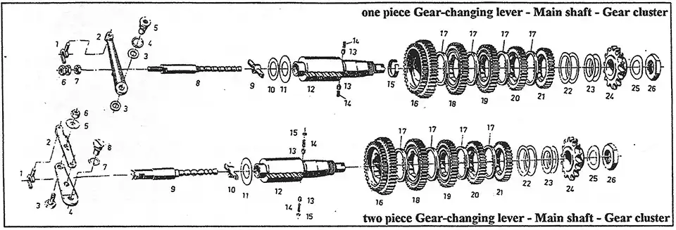
Internal pieces to check (refer to parts illustration #1) - Selector rod #9 grooved by #13, 14, 15 plunger cup.
- Plunger cups frozen, missing, or badly worn.
- Selector Key #9-10 worn (very important).
- Sliding gears #18, 19 - 2nd & 3rd key contact areas not rounded. All the above in the main shaft assembly should move without binding and be free, with the plunger detents working the shaft into the detents smoothly.
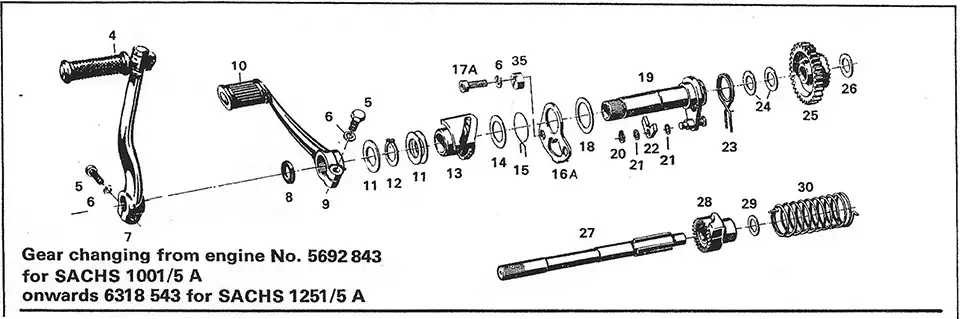
Shifter assembly (refer to parts illustration #2) - Check that the pawl spring # 15 is making contact on both sides of the selector pawl #22. This is important as this moves the selector pawl #22 into place against the teeth of the selector boss # 13.
- This whole assy., shifter assy. #12-23 is shimmed together. It must move free within itself, but no slop.
NOTE: To adjust shifting, the clutch gear assy. must be
removed!!!
INSTALLING THE SHIFTER ASSEMBLY
The shifter assy. must be shimmed, use shims #24. These fit over the kick starter shaft at the base against the cases. Slide the assy., down over the kick start shaft #27, the adjusting plate # 16 should make contact with the mounts just before the shifter assy. bottoms out. The adjusting plate #16A needs to be in a non-binding position. After shims are .determined, slide the shaft assy. back up the kick start . shaft and install the shifting fork, selector arm and pivot screw, all wile sliding the assy. back down. Install mounting bolts with cams and tighten with the cams moved out of the way. Using shims #11, shim the shifter assy. so you can put a straight edge across the cases and the selector assy. making contact at all three places. NOTE: if the selector arm has an overly amount of play at the pivot point you may need to find a shim washer to eliminate some of the slop. This is rare, but it does happen. If you have now said: "Okay, I'm ready", we will move on to the adjusting procedures.
A special tool here is a must. It is called the "Transmission Adjusting Tool" and is not a Sachs item. Ted Penton made this tool for the Penton service dept. and the Penton parts list and the "Hi-Point Accessories" catalog. It or a reproduction of this tool is available thru Buehners Supply (phone #216-651-6559). The reason for this tool is to simulate what the left side cover does when the engine is together. It is impossible to make accurate adjustments without this tool. You may get lucky once in awhile, but to be sure, use the tool.
Step one: Make sure you can shift from 1st thru 5th or 6th (which ever you are working on). The bolt in the middle of the selector arm is a concentric ( on the later engines). I will make a separate procedure for the early 5 A engines. Bend back the locking tab on the top and loosen the 10mm nut if you need to move the concentric 13mm bolt. The object is to have equal movement up and down against the selector rod #9. If you can get full engagement of 1st and 5th or 6th, it means you are now inside the ball park.
Step two: Now we want to work between 3rd and 4th gear. NOTE: I usually put the shift lever in about a 7 o'clock position for ease of holding it in position (engine or bike laying right side down) while I turn the counter shaft sprocket or the clutch inner hub. Please do not try to make these adjustments with the clutch assembly still in place. If you can get 3rd and 4th lined up, it makes things go a lot easier, but this is not an absolute. Move the shift lever to engage 4th and hold the lever tight up. Reach in with your fingers and see if you can feel more up pressure or down pressure of the fork # I against the selector rod #8 or 9. It is perfect if the fork is loose while you are still holding up pressure on the shift lever.
Move the shift lever down to engage 3rd gear, again holding pressure, now down, on the . shift lever. Reach in and feel where the pressure is between the two. If the fork is loose in the slot with down pressure on the shift lever again, this is perfect. Most of the time (95%) you will have to determine which way to turn the concentric (13mm) to add either more up or down movement on the selector rod. You are moving the selector rod, but checking the movement using the shifter fork. Once you can feel that you have equal pressure in both directions, tighten the 10mm nut and try again. And again, then shift from 1st thru 5 or 6 and back. At this time I check my fork pressure in the high gear and the low gear, again they should be the same, IF the 3rd and 4th adjustments were the same.
Now loosen and set the left cam, upshift to any gear (3rd or 4th) holding the shift lever tight up, move the cam over to make contact with the pawl, and tighten the alien head. Make sure the pawl does not make contact with the cam before the selector is all the way. Repeat the procedure for the right cam, but you will need three hands and a small crew driver to hold the shift lever tight down. Move and hold the cam in place while you tighten the mounting alien head. Okay, now shift thru all gears until you are happy. Make sure you have tightened everything, and put the lock tab back on the 10mm nut on the selector arm. Remove the tool, reassemble the engine and go have fun.
Here are 10 very important items to check:
(Taken from a previous article by Kip Kern.)
refer to illustration #1
- The main shaft #12 is shimmed properly between the case halves.
- The shift key #9 is in excellent condition.
- The selector rod #8-9 is not grooved or worn.
- The selector rod detents #13-14 are in excellent condition.
- The transmission gears are spaced properly and not worn on the insides.
- The two springs #15-23 on the shifter assy. are OK, making contact equally against the pawls.
- The shifter assy. is shimmed properly, from the inner case.
- The space between the shifter assy. and the clutch cover (special tool) are shimmed properly, prior to installation of the clutch assy.
- Properly shim the shift arm pivot point in the case.
- Use an unworn shift fork #1.